Manuals
/
Teledyne
/
Household Appliance
/
Electric Heater
Teledyne
EHE
warranty
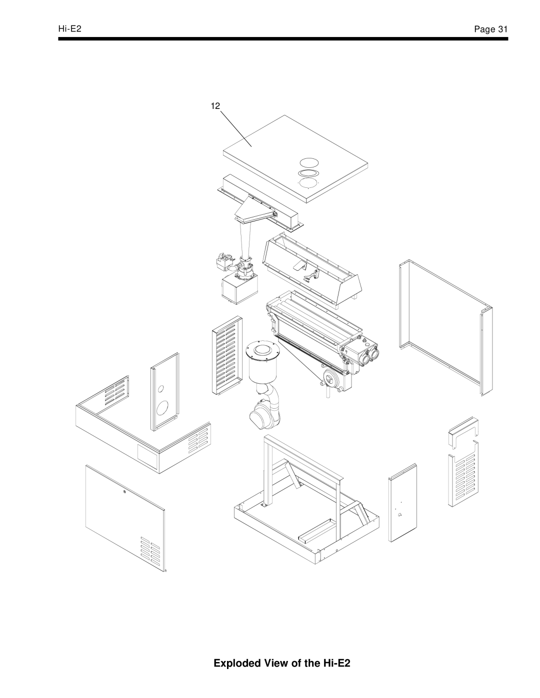
Exploded View of the Hi-E2
Models:
EHE
1
33
34
34
Download
34 pages
50.86 Kb
27
28
29
30
31
32
33
34
Page 33
Image 33
Hi-E2
Page 31
12
Exploded View of the
Hi-E2
Page 32
Page 34
Page 33
Image 33
Page 32
Page 34
Contents
Installation Hi-E2 Model EHE Gas-Fired Pool Spa Heater
Table of Contents
General Information
Installation Instructions
2D. Installation Clearances
2B. Heater Assembly and Preparation
2E. Outdoor Installation
Installation at High Elevation
2G. Indoor Installation
2F. Outdoor Shelter Installation Canada
2G-1. Preparation of Heater For Indoor Installation
United States
2G-3. Two-Pipe Installation Direct Vent
2G-2. Combustion Air Requirements for One-Pipe Installation
2G-3a. Connection of Combustion Air Pipe
2G-3b. Piping Materials
Installation
2G-3d. Combustion Air and Vent Pipe
2G-3c. Size and Length of Combustion Air and Vent Piping
Indoor Vent Connection, Hi-E2 Pool Heater
2H. Condensate Disposal
2G-3e. Room Ventilation
2I. Gas Supply and Piping
60Hz
High Elevation
2J-1. Electrical Power
2J. Electric Wiring
2J-3. Auxiliary Time Clock Wiring
2J-2. Bonding
2K. Water Piping
2K-1. Reversal of Heater Water Connections
2K-3. Connections at Heater
2K-5. Automatic Chlorinators Chemical Feeders
2K-4. Pressure Relief Valve
2L-1. Normal Operation
2L. Start-up and Adjustment
2L-2. Start-up
2L-5. Adjustment of Water Pressure Switch
2L-3. Condensate
2L-4. Gas Pressure
Operating Instructions
2L-6. Water Temperature Rise
3B. Temperature Controls
3A. Start-Up Procedure
3D. Water Chemistry
3C. Lighting and Shutdown
3D-2d. Testing
3E. Spa/Hot Tub Safety Rules
3F. Swimming Pool Energy Savings Tips
3D-2c. Corrosion
3H. Periodic Inspection
3G. Seasonal Care
3G-1. Spring and Fall Operation
3G-2. Winterizing
Maintenance and Service
4A. General
3H-2. Professional Inspection
4C. Heater Components and Their Operation
4B. Induced-Draft Combustion System
4E. Electrical Trouble Shooting
4E-1 V Electrical Power Supply
4D. Combustion Air Filter
4E-2. Control Circuit Trouble Shooting
4E-2a. Transformer
4E-2b. Fuse
4E-2d. Limit Switches
4E-2c. Fireman Switch and External Interlocks
4E-2e. Water Pressure Switch
4E-2f. Temperature Control
4F. Venturi Combustion Flow System
4F-2a. Unfired Venturi Differential Pressure
4F-2. Venturi System Checkout
4F-2b. Gas Pressure Offset
4F-2c. Gas Orifice Differential
4F-3a. Combustion Air Flow
4F-3. Air Flow Investigation
4F-3b. Flow in Heater and Vent
4G. Combustion Condensate
4F-4. Fuel Gas Type and Gas Orifice Size
4F-5. High Elevation Operation
Capacities and Dimensions
4H. Major Component Service
5A. General Information
6A. Parts List
Replacement Parts
Exploded View of the Hi-E2
Limited Warranty
Top
Page
Image
Contents