Installation
THE ANALYZER WITH ITS FASTENING SCREWS. ULTIMATELY, IT IS THE INSTALLER WHO ENSURES THAT THE CONNECTIONS PROVIDE ADEQUATE EMI/RFI SIELDING.
3.3.3.1PRIMARY INPUT POWER
The power cord receptacle and fuse block are located in the same assembly. Insert the power cord into the power cord receptacle.
CAUTION: POWER IS APPLIED TO THE INSTRUMENT'S CIRCUITRY AS LONG AS THE INSTRUMENT IS CONNECTED TO THE POWER SOURCE.
The standard power supply requires 110 VAC, 50/60 Hz or 220 VAC, 50/60 Hz (optional) power.
3.3.3.2FUSE INSTALLATION
The fuse block, at the right of the power cord receptacle, accepts US or European size fuses. A jumper replaces the fuse in whichever fuse receptacle is not used.
3.3.3.3
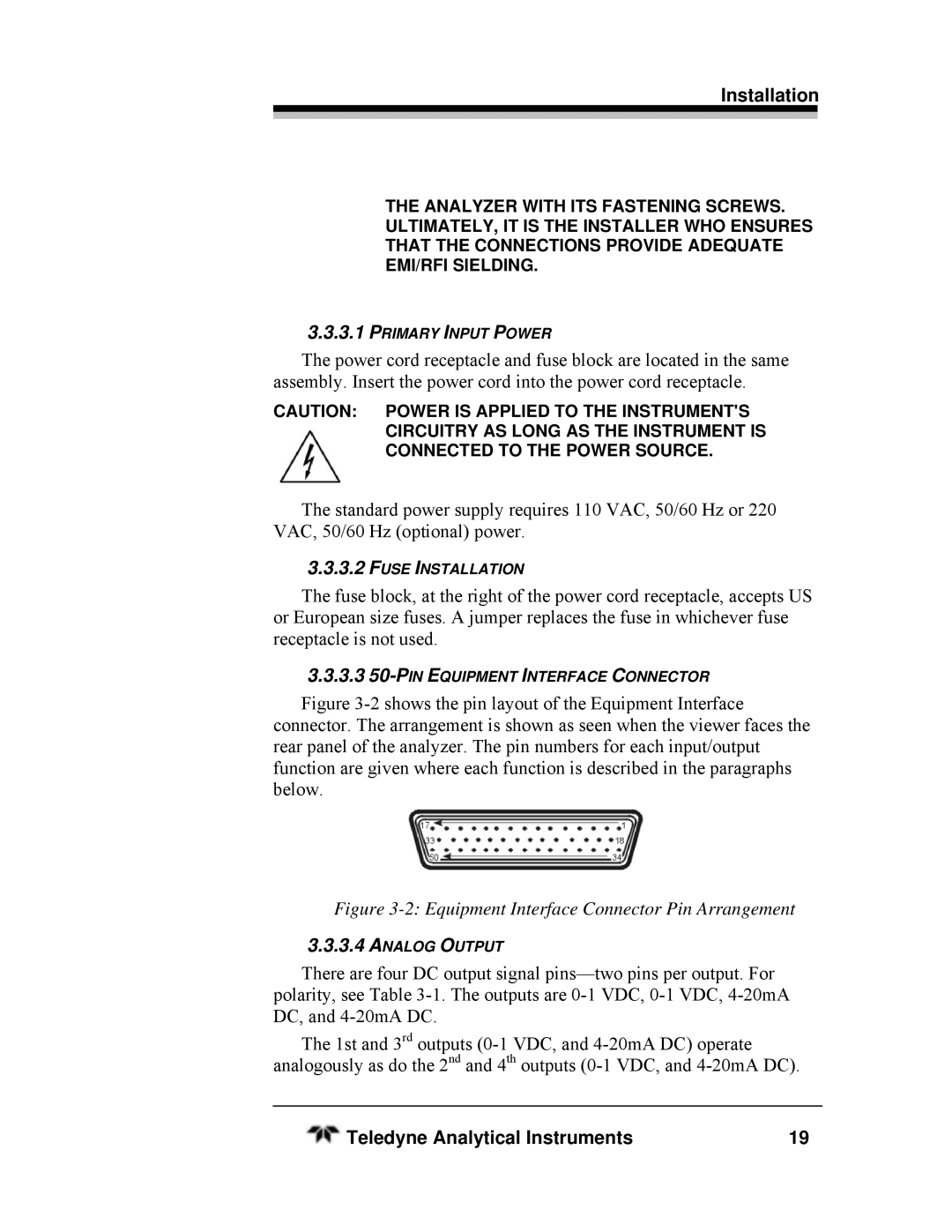
Figure 3-2 shows the pin layout of the Equipment Interface connector. The arrangement is shown as seen when the viewer faces the rear panel of the analyzer. The pin numbers for each input/output function are given where each function is described in the paragraphs below.
Figure 3-2: Equipment Interface Connector Pin Arrangement
3.3.3.4ANALOG OUTPUT
There are four DC output signal
The 1st and 3rd outputs
Teledyne Analytical Instruments | 19 |