Installation
3.3.3.7NETWORK I/O
A serial digital input/output for local network protocol. At this printing, this port is not yet functional. It is to be used in future options to the instrument. Pins 13 (+) and 29
3.3.3.8 Pin Out Table
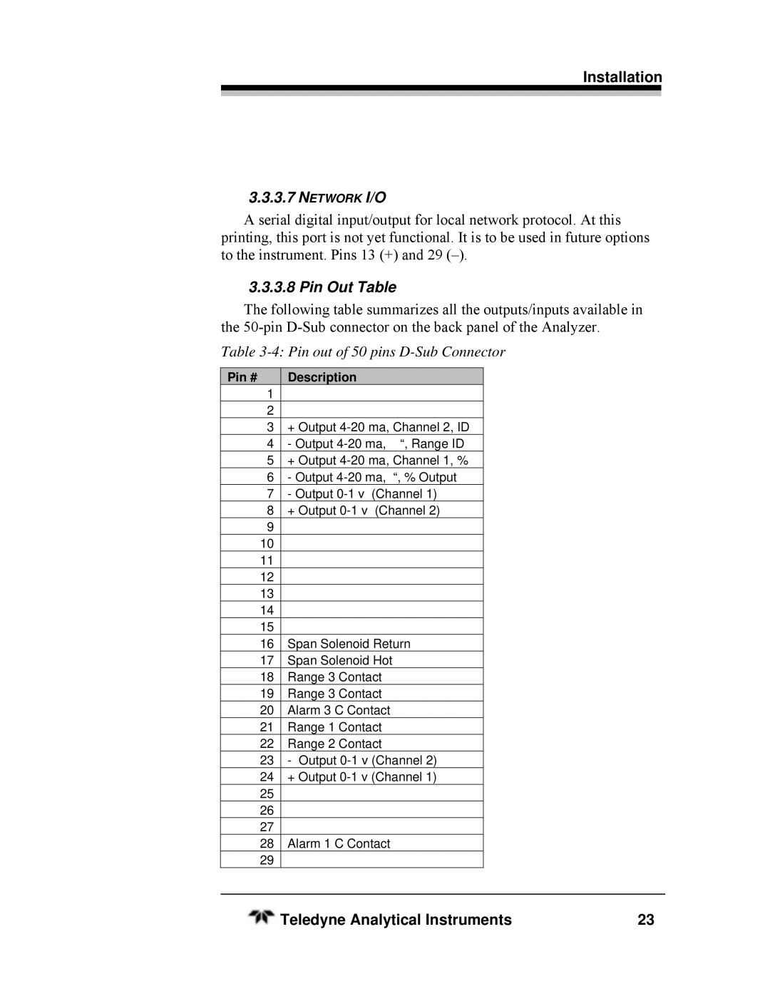
The following table summarizes all the outputs/inputs available in the
Table 3-4: Pin out of 50 pins D-Sub Connector
Pin # | Description |
1 |
|
2 |
|
3 | + Output |
4 | - Output |
5 | + Output |
6 | - Output |
7 | - Output |
8 | + Output |
9 |
|
10 |
|
11 |
|
12 |
|
13 |
|
14 |
|
15 |
|
16 | Span Solenoid Return |
17 | Span Solenoid Hot |
18 | Range 3 Contact |
19 | Range 3 Contact |
20 | Alarm 3 C Contact |
21 | Range 1 Contact |
22 | Range 2 Contact |
23 | - Output |
24 | + Output |
25 |
|
26 |
|
27 |
|
28 | Alarm 1 C Contact |
29 |
|
Teledyne Analytical Instruments | 23 |