Section
4
FM-1 Frequency Manager
Front Panel Controls and Connections
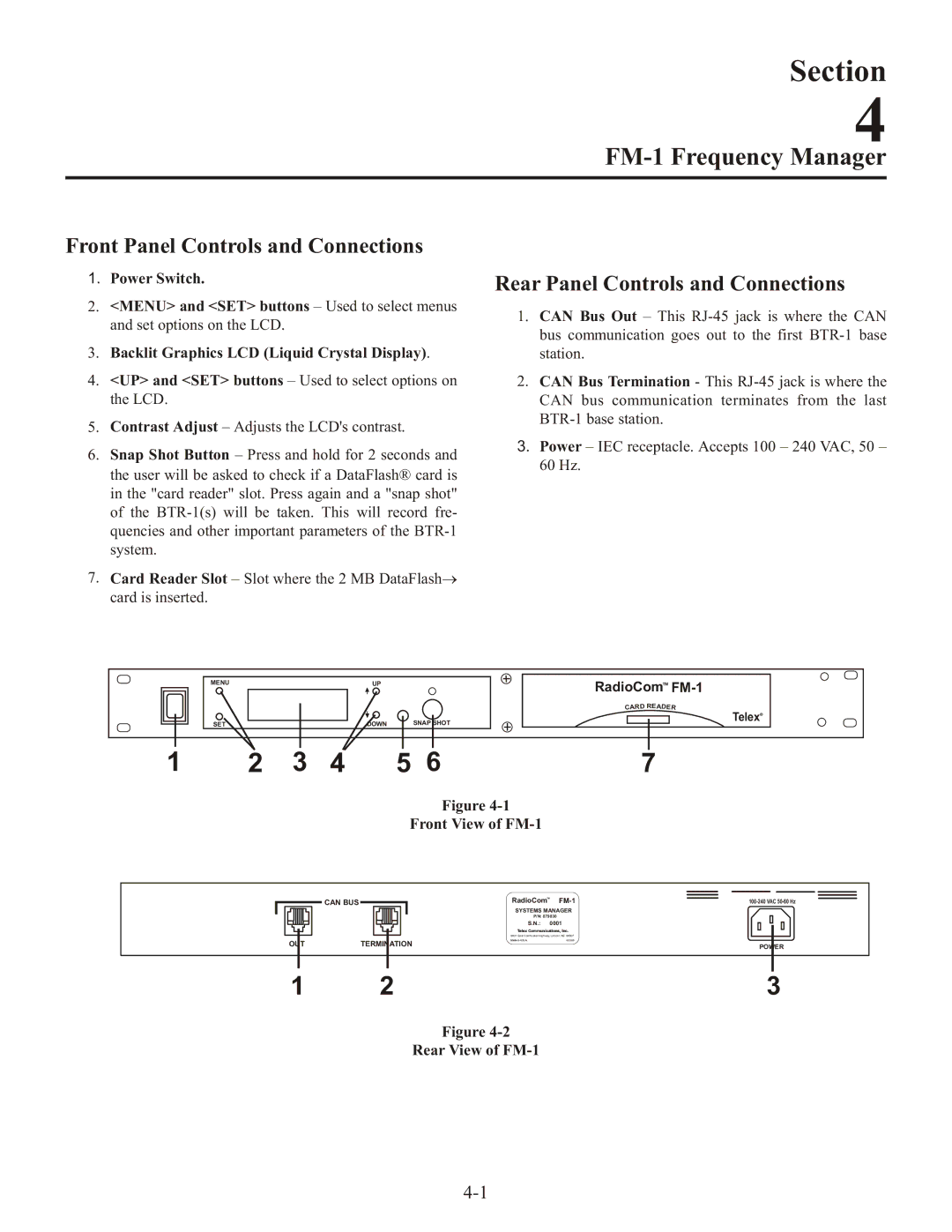
1.Power Switch.
2.<MENU> and <SET> buttons – Used to select menus and set options on the LCD.
3.Backlit Graphics LCD (Liquid Crystal Display).
4.<UP> and <SET> buttons – Used to select options on the LCD.
5.Contrast Adjust – Adjusts the LCD's contrast.
6.Snap Shot Button – Press and hold for 2 seconds and the user will be asked to check if a DataFlash® card is in the "card reader" slot. Press again and a "snap shot" of the
7.Card Reader Slot – Slot where the 2 MB DataFlash→ card is inserted.
Rear Panel Controls and Connections
1.CAN Bus Out – This
2.CAN Bus Termination - This
3.Power – IEC receptacle. Accepts 100 – 240 VAC, 50 – 60 Hz.
MENU |
|
| UP |
| RadioComTM | |
|
|
|
|
| D | A |
|
|
|
|
| CAR | RE DER |
SET |
|
| DOWN | SNAP SHOT |
| TelexR |
|
|
|
| |||
1 | 2 | 3 | 4 | 5 6 | 7 | |
Figure
Front View of FM-1
CAN BUS
RadioComTM |
|
SYSTEMS MANAGER
P/N: 879830
S.N.: 0001
|
|
| Telex Communications, Inc. | |
|
|
| 8601 East Cornhusker Highway, Lincoln, NE 68507 | |
OUT |
|
| Made in U.S.A. | 803995 |
TERMINATION | POWER | |||
1 | 2 | 3 |
Figure