| FM-1 Specifications |
Temperature Range | -4°F to 130°F (-20°C to 55°C) |
Dimensions | 19.0”W x 1.72”H x 8.02”D |
| (48.3 cm x 4.4 cm x 20.4 cm) |
Weight | 3 lbs 9 oz (1.62 kg) |
Memory Card Type | DataFlash®, 2 MB Only |
Event Storage | Up to 99 Events |
Power Requirements | 100 – 240 VAC, 50 – 60 Hz, IEC receptacle |
Communication Bus | CAN Bus |
| |
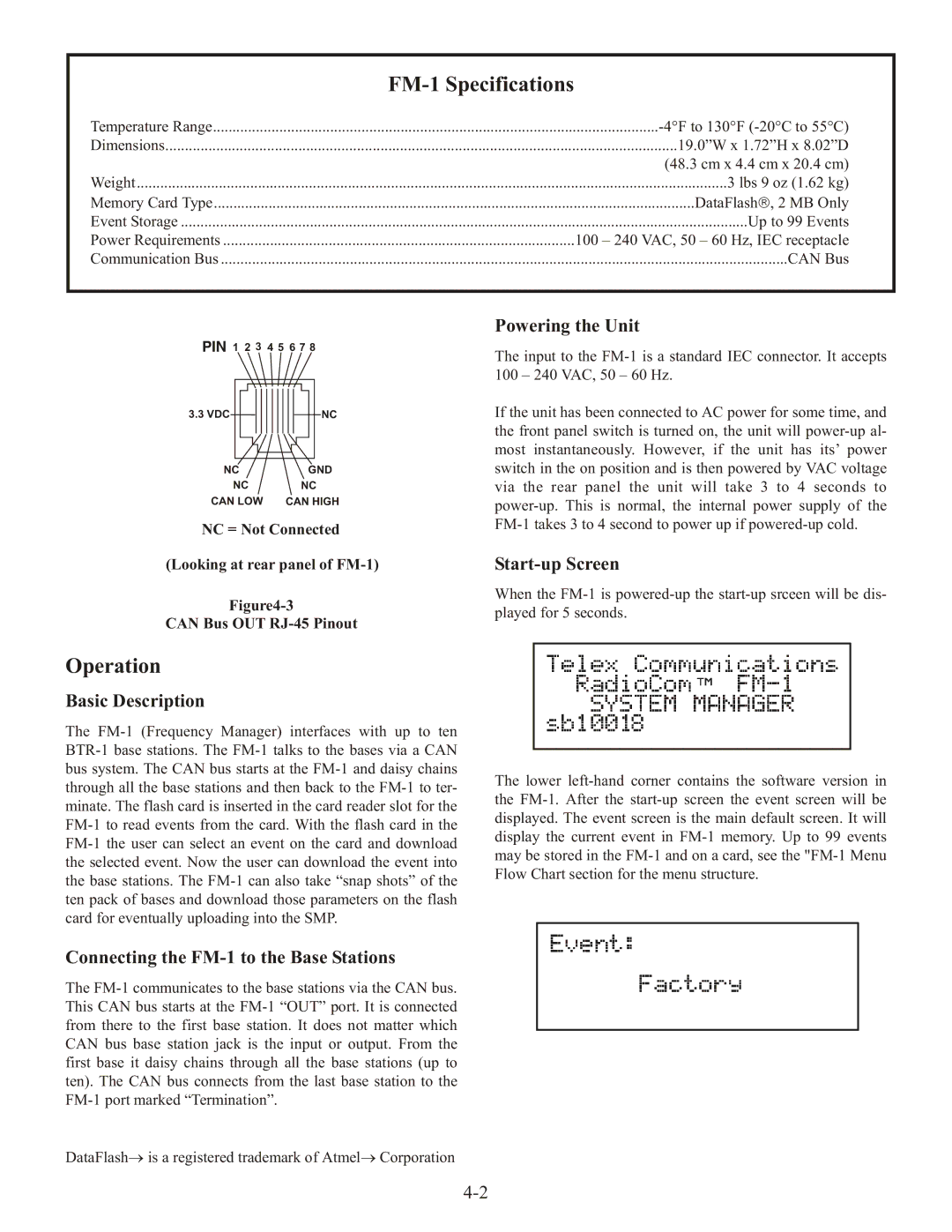
PIN 1 2 3 4 5 6 7 8
3.3 VDC | | | | | | | | | | NC |
| | | | | | | | |
| | | | | | | | | | |
| | | | | | | | |
NC | | | | | | GND |
NC | | | | | | NC |
CAN LOW | | | | CAN HIGH |
NC = Not Connected
(Looking at rear panel of FM-1)
Figure4-3
CAN Bus OUT RJ-45 Pinout
Powering the Unit
The input to the FM-1 is a standard IEC connector. It accepts 100 – 240 VAC, 50 – 60 Hz.
If the unit has been connected to AC power for some time, and the front panel switch is turned on, the unit will power-up al- most instantaneously. However, if the unit has its’ power switch in the on position and is then powered by VAC voltage via the rear panel the unit will take 3 to 4 seconds to power-up. This is normal, the internal power supply of the FM-1 takes 3 to 4 second to power up if powered-up cold.
Start-up Screen
When the FM-1 is powered-up the start-up srceen will be dis- played for 5 seconds.
Operation
Basic Description
The FM-1 (Frequency Manager) interfaces with up to ten BTR-1 base stations. The FM-1 talks to the bases via a CAN bus system. The CAN bus starts at the FM-1 and daisy chains through all the base stations and then back to the FM-1 to ter- minate. The flash card is inserted in the card reader slot for the FM-1 to read events from the card. With the flash card in the FM-1 the user can select an event on the card and download the selected event. Now the user can download the event into the base stations. The FM-1 can also take “snap shots” of the ten pack of bases and download those parameters on the flash card for eventually uploading into the SMP.
Connecting the FM-1 to the Base Stations
The FM-1 communicates to the base stations via the CAN bus. This CAN bus starts at the FM-1 “OUT” port. It is connected from there to the first base station. It does not matter which CAN bus base station jack is the input or output. From the first base it daisy chains through all the base stations (up to ten). The CAN bus connects from the last base station to the FM-1 port marked “Termination”.
The lower left-hand corner contains the software version in the FM-1. After the start-up screen the event screen will be displayed. The event screen is the main default screen. It will display the current event in FM-1 memory. Up to 99 events may be stored in the FM-1 and on a card, see the "FM-1 Menu Flow Chart section for the menu structure.
DataFlash→ is a registered trademark of Atmel→ Corporation

