|
|
|
| Gain Variable Volume Control VR1 | |
Table 2±5. Gain Mode Switch SW2 |
|
| |||
|
|
|
|
|
|
|
| Switch No. | Gain Mode | ||
|
|
|
|
|
|
|
| Left | AGC | ||
|
| Center | Fixed | ||
|
| Right | Variable |
| |
Figure 2±3. Gain Mode Switch SW2 |
|
| |||
|
|
|
|
|
|
|
|
|
|
|
|
Left Right
Center
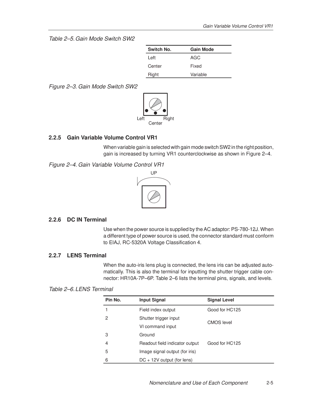
2.2.5Gain Variable Volume Control VR1
When variable gain is selected with gain mode switch SW2 in the right position, gain is increased by turning VR1 counterclockwise as shown in Figure 2±4.
Figure 2±4. Gain Variable Volume Control VR1
UP
2.2.6DC IN Terminal
Use when the power source is supplied by the AC adaptor:
2.2.7LENS Terminal
When the
Table 2±6. LENS Terminal
Pin No. | Input Signal | Signal Level |
|
|
|
1 | Field index output | Good for HC125 |
2 | Shutter trigger input | CMOS level |
| VI command input | |
|
| |
3 | Ground |
|
4 | Readout field indicator output | Good for HC125 |
5 | Image signal output (for iris) |
|
6 | DC + 12V output (for lens) |
|
Nomenclature and Use of Each Component |