www.ti.com
ChronosGUI
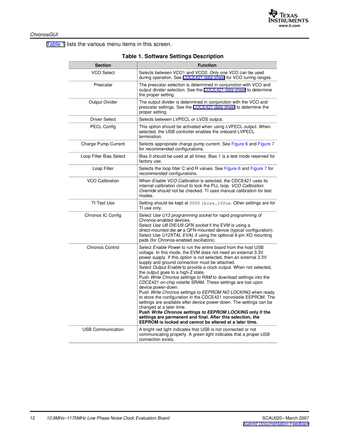
Table 1 lists the various menu items in this screen.
Table 1. Software Settings Description
Section
Function
VCO Select | Selects between VCO1 and VCO2. Only one VCO can be used |
| during operation. See CDCE421 data sheet for VCO tuning ranges. |
Prescalar | The prescalar selection is determined in conjunction with VCO and |
| output divider selection. See the CDCE421 data sheet to determine |
| the proper setting. |
Output Divider | The output divider is determined in conjunction with the VCO and |
| prescalar settings. See the CDCE421 data sheet to determine the |
| proper setting. |
Driver Select | Selects between LVPECL or LVDS output. |
PECL Config | This option should be activated when using LVPECL output. When |
| selected, the USB controller enables the onboard LVPECL |
| termination. |
Charge Pump Current | Selects appropriate charge pump current. See Figure 6 and Figure 7 |
| for recommended configurations. |
Loop Filter Bias Select | Bias 0 should be used at all times. Bias 1 is a test mode reserved for |
| factory use. |
Loop Filter | Selects the loop filter C and R values. See Figure 6 and Figure 7 for |
| recommended configurations. |
VCO Calibration | When Enable VCO Calibration is selected, the CDCE421 uses its |
| internal calibration circuit to lock the PLL loop. VCO Calibration |
| Override should not be checked. TI uses manual calibration for test |
| modes. |
TI Test Use | Setting should be kept at 0000 ibias_100ua. Other settings are for |
| TI use only. |
Chronos IC Config | Select Use U13 programming socket for rapid programming of |
| |
| Select Use U8 DIE/U9 QFN socket if the EVM is using a |
| |
| Select Use U12XTAL EVAL if using the optional |
| pads (for |
Chronos Control | Select Enable Power to run the entire board from the host USB |
| voltage. In this mode, the EVM does not need an external 3.3V |
| power supply. If this option is not selected, then an external 3.3V |
| supply and ground connection must be attached. |
| Select Output Enable to provide a clock output. When not selected, |
| the output goes to a |
| Push Write Chronos settings to RAM to download settings into the |
| CDCE421 |
| device |
| Push Write Chronos settings to EEPROM NO LOCKING when ready |
| to store the configuration in the CDCE421 nonvolatile EEPROM. The |
| settings are available after device |
| changed at a later time. |
| Push Write Chronos settings to EEPROM LOCKING only if the |
| settings are permanent and final. After this selection, the |
| EEPROM is locked and cannot be altered at a later time. |
USB Communication | A bright red light indicates that USB is not connected or not |
| communicating properly. A green light indicates that a proper USB |
| connection exists. |
12 | SCAU020 |
