4.6.Network View
The PC demo will always display one node on the top of the screen, the Sink. Below the Sink the presence of additional network nodes will be displayed as they are detected. Be aware that nodes may place themselves on top of existing nodes when they first appear, but can easily be dragged away with the mouse.
The various states of the nodes are described below.
Sink node not connected to the PC.
An attempt to read from the COM port has been made, but no response received.
Sink node connected to the PC but reading from the COM port is not active.
Sink node connected to the PC and reading from the COM port. The difference with a Sink not connected to the PC can be seen from the black and white outline.
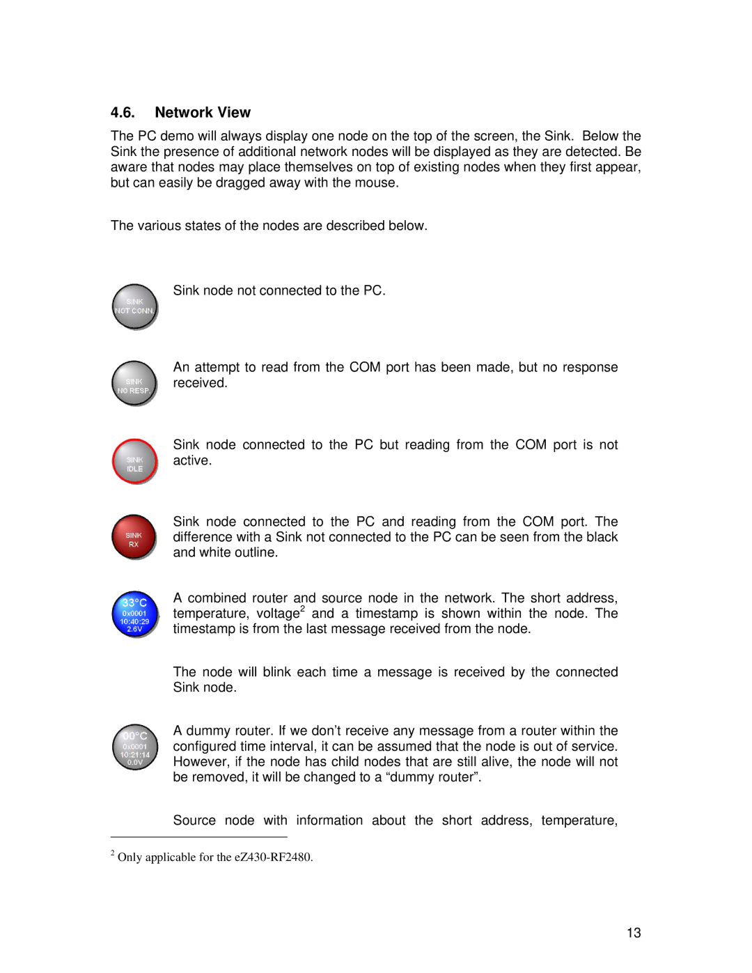
A combined router and source node in the network. The short address, temperature, voltage2 and a timestamp is shown within the node. The timestamp is from the last message received from the node.
The node will blink each time a message is received by the connected Sink node.
A dummy router. If we don’t receive any message from a router within the configured time interval, it can be assumed that the node is out of service. However, if the node has child nodes that are still alive, the node will not be removed, it will be changed to a “dummy router”.
Source node with information about the short address, temperature,
2Only applicable for the
13