Precautions
2.1 Precautions
Power Supply Input Polarity and Maximum Voltage
Always ensure that the polarity and voltage of the external power connected to VCC power input connector J1, J2, and/or VDD power input connector J6 are correct. Overvoltage or
Inserting or Removing EVM Boards
Do not insert or remove EVM boards with power applied ± damage to the EVM board, the platform, or both may result.
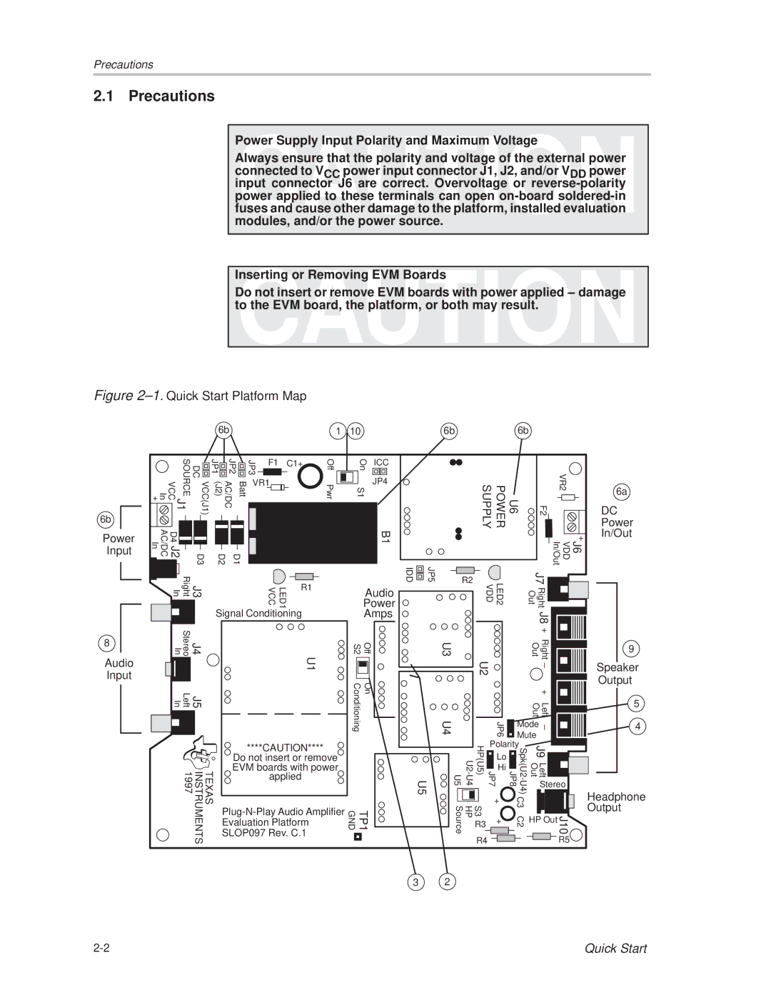
Figure 2±1. Quick Start Platform Map
6b | 1 | 10 |
6b
6b |
6b
Power Input
|
| SOURCE | DC |
In + | VCC | J1 | VCC(J1) |
AC/DC In | J2 | D3 | |
| D4 |
|
|
JP1 (J2)
D2
| JP2 |
|
| JP3 | F1 |
| |||
|
|
|
|
|
|
|
| ||
AC/DC | Batt | VR1 |
|
| |||||
|
| ||||||||
|
|
|
|
| |||||
|
|
|
|
| |||||
|
|
|
|
|
|
| |||
|
|
|
|
|
|
|
|
|
|
|
|
|
|
|
|
|
|
|
|
|
|
|
|
|
|
|
|
|
|
|
|
|
|
|
|
|
|
|
|
|
|
|
|
|
|
|
|
|
|
|
| D1 |
|
|
|
|
| ||
|
|
|
|
|
|
| |||
C1+
Off |
| On | ICC |
|
|
| |
|
|
| JP4 |
|
|
| |
Pwr |
| S1 |
|
B1
U6 POWER SUPPLY |
| VR2 | 6a |
F2 | DC | ||
Power | |||
|
| + | In/Out |
|
| J6 VDD In/Out |
|
8
Audio Input
|
|
|
|
|
|
|
|
|
| Right In | J3 | ||
|
|
|
|
|
| |
|
|
|
|
|
|
|
|
|
|
|
|
|
|
|
|
|
|
|
|
|
|
|
| Stereo In | J4 | ||
|
|
|
|
|
|
|
|
|
|
|
|
|
|
|
|
|
|
|
| |
|
|
| Left In | J5 | ||
|
|
|
|
|
|
|
|
|
|
|
|
|
|
|
|
|
|
|
|
|
|
|
|
|
|
|
|
INSTRUMENTS 1997
LED1 VCC | R1 |
|
Signal Conditioning
U1
| ****CAUTION**** | |
| Do not insert or remove | |
TEXAS | EVM boards with power | |
applied | ||
|
Evaluation Platform
SLOP097 Rev. C.1
IDD | JP5 |
| Audio |
| Power |
| Amps |
S2 | Off |
Conditioning | On |
U5
TP1
GND
R2
U3
U4
U5 | |||
|
|
| |
|
|
|
|
Source | HP | ||
LED2 VDD |
| J7 |
|
| ||
| Right Out |
|
| |||
|
|
|
| J8 + |
|
|
|
|
| Out | Right |
| 9 |
U2 |
|
|
| Speaker | ||
|
|
| ± |
| ||
|
|
|
| Output | ||
|
|
|
|
|
| |
|
|
|
| + |
|
|
|
|
| Left Out |
| 5 | |
|
|
|
|
| ||
| JP6 | Mode | ± |
| 4 | |
| Mute |
|
| |||
|
|
|
|
| ||
HP(U5) | Polarity | J9 |
|
| ||
Lo |
|
|
| |||
Out | Left |
|
| |||
Hi |
|
| ||||
JP7 |
|
| ||||
Stereo |
| |||||
|
| Headphone | ||||
| + | C3 |
|
|
| |
S3 |
|
| J10 | Output | ||
HP Out |
| |||||
R3 | + | C2 |
| |||
|
|
| ||||
|
|
|
| |||
R4 |
|
|
|
| R5 |
|
3 2
Quick Start |