The TPA701 MSOP Audio Power Amplifier Evaluation Module
3.2 The TPA701 MSOP Audio Power Amplifier Evaluation Module
The TPA701 MSOP Audio Power Amplifier Evaluation Module is powered by a TPA701
The module can be used with the TI
The module connection pins are on
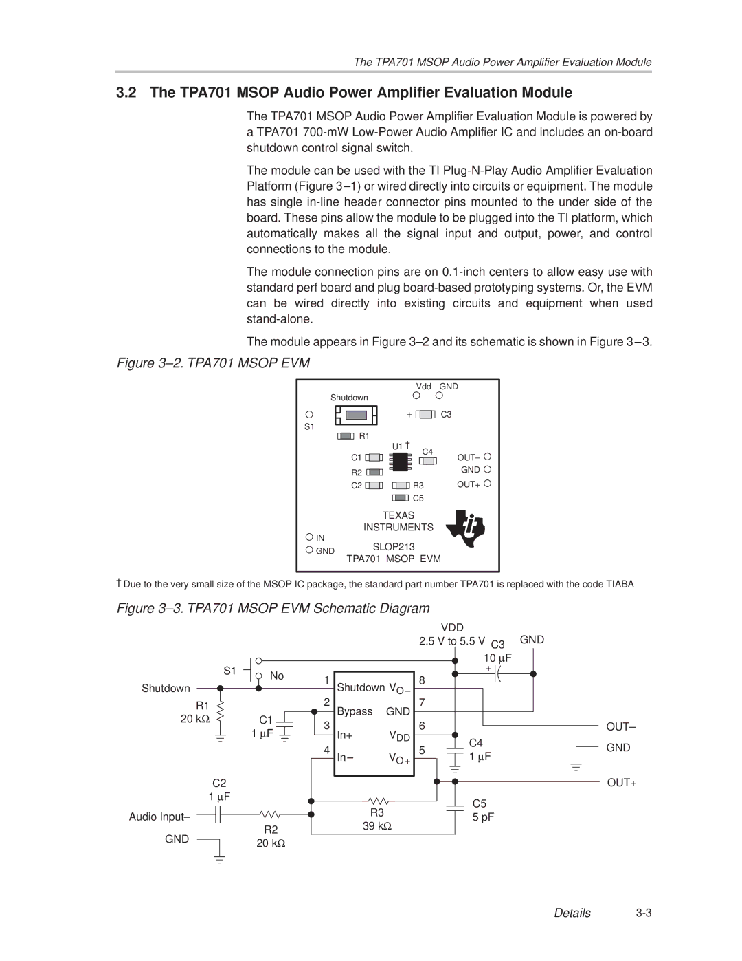
The module appears in Figure 3±2 and its schematic is shown in Figure 3±3.
Figure 3±2. TPA701 MSOP EVM
Vdd
Shutdown
S1 |
|
|
|
|
|
|
|
|
| + | ||
|
|
|
|
|
|
|
|
| ||||
|
|
|
|
|
|
|
|
| ||||
|
| R1 | ² |
|
| |||||||
|
|
|
|
|
| |||||||
|
|
|
|
|
| |||||||
|
|
|
|
|
|
|
|
| U1 |
| C4 | |
|
|
| C1 |
|
|
|
| |||||
|
|
| R2 |
|
|
|
|
|
| |||
|
|
|
|
|
|
|
|
| ||||
|
|
|
|
|
|
|
|
| ||||
|
|
|
| |||||||||
|
|
| C2 |
|
| R3 | ||||||
|
|
|
|
|
|
|
|
|
|
|
| C5 |
|
|
|
|
|
|
|
|
|
|
|
| |
|
|
|
|
|
|
|
|
|
|
|
| |
GND
C3
OUT± ![]()
GND ![]()
OUT+ ![]()
| TEXAS | |
| INSTRUMENTS | |
IN | SLOP213 | |
GND | ||
TPA701 MSOP EVM | ||
|
²Due to the very small size of the MSOP IC package, the standard part number TPA701 is replaced with the code TIABA
Figure 3±3. TPA701 MSOP EVM Schematic Diagram |
|
| |||||
|
|
|
|
|
| VDD | GND |
|
|
|
|
| 2.5 V to 5.5 V C3 | ||
|
|
|
|
|
| 10 μF |
|
S1 | No | 1 |
|
|
| + |
|
|
| 8 |
|
| |||
Shutdown | Shutdown V |
|
| ||||
|
|
| |||||
|
| 2 |
| O ± | 7 |
|
|
R1 |
| Bypass | GND |
|
| ||
|
|
|
|
| |||
20 kΩ | C1 |
|
|
|
| ||
3 |
|
| 6 |
| OUT± | ||
| 1 μF | In+ | VDD |
| |||
|
|
| C4 | GND | |||
|
| 4 |
|
| 5 | ||
|
| In± | VO + | 1 μF | |||
|
|
| |||||
C2 |
|
|
|
|
|
| OUT+ |
1 μF |
|
|
|
|
| C5 |
|
|
|
| R3 |
|
|
| |
Audio Input± |
|
|
|
| 5 pF |
| |
|
| 39 kΩ |
|
| |||
| R2 |
|
|
|
| ||
GND |
|
|
|
|
|
| |
20 kΩ |
|
|
|
|
|
| |
|
|
|
|
|
|
| |
Details