Quick Start List for
2.3 Quick Start List for Stand-Alone
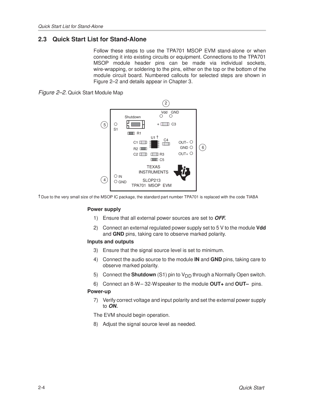
Follow these steps to use the TPA701 MSOP EVM
Figure 2±2. Quick Start Module Map
|
| 2 |
|
|
| Vdd | GND |
| Shutdown |
|
|
5 |
| + | C3 |
| S1 |
|
|
| R1 | U1 ² |
|
|
|
| |
| C1 | C4 | OUT± |
|
| ||
| R2 |
| GND |
|
|
| |
| C2 | R3 | OUT+ |
|
| C5 |
|
|
| TEXAS |
|
| INSTRUMENTS |
| |
4 | IN | SLOP213 |
|
GND |
| ||
| TPA701 MSOP EVM | ||
6
²Due to the very small size of the MSOP IC package, the standard part number TPA701 is replaced with the code TIABA
-Power supply
1)Ensure that all external power sources are set to OFF.
2)Connect an external regulated power supply set to 5 V to the module Vdd and GND pins, taking care to observe marked polarity.
-Inputs and outputs
3)Ensure that the signal source level is set to minimum.
4)Connect the audio source to the module IN and GND pins, taking care to observe marked polarity.
5)Connect the Shutdown (S1) pin to VDD through a Normally Open switch.
6)Connect an
-Power-up
7)Verify correct voltage and input polarity and set the external power supply to ON.
The EVM should begin operation.
8) Adjust the signal source level as needed.
Quick Start |