Using The TPA701 MSOP EVM With the
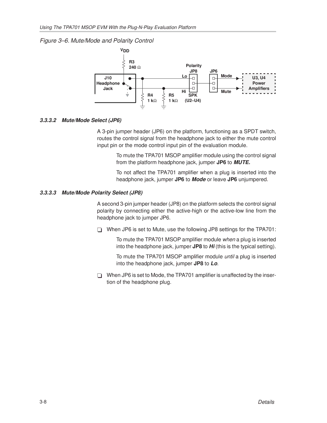
Figure 3±6. Mute/Mode and Polarity Control
| VDD |
|
| R3 | Polarity |
| 240 Ω | |
| JP8 | |
|
| |
J10 |
| Lo |
|
|
Headphone
Jack |
| Hi | |
R4 | R5 | ||
SPK | |||
1 kΩ | 1 kΩ | (U2±U4) |
JP6
|
|
|
| Mode | U3, U4 |
|
|
| |||
|
|
|
|
| |
|
|
|
|
| Power |
|
|
|
|
| |
|
|
|
|
| Amplifiers |
|
|
|
| Mute | |
|
|
|
|
| |
|
|
|
|
| |
|
|
|
|
|
|
3.3.3.2Mute/Mode Select (JP6)
A
JTo mute the TPA701 MSOP amplifier module using the control signal from the platform headphone jack, jumper JP6 to MUTE.
JTo not affect the TPA701 amplifier when a plug is inserted into the headphone jack, jumper JP6 to Mode or leave JP6 unjumpered.
3.3.3.3Mute/Mode Polarity Select (JP8)
A second
-When JP6 is set to Mute, use the following JP8 settings for the TPA701:
J To mute the TPA701 MSOP amplifier module when a plug is inserted into the headphone jack, jumper JP8 to Hi (this is the typical setting).
J To mute the TPA701 MSOP amplifier module until a plug is inserted into the headphone jack, jumper JP8 to Lo.
-When JP6 is set to Mode, the TPA701 amplifier is unaffected by the inser- tion of the headphone plug.
Details |