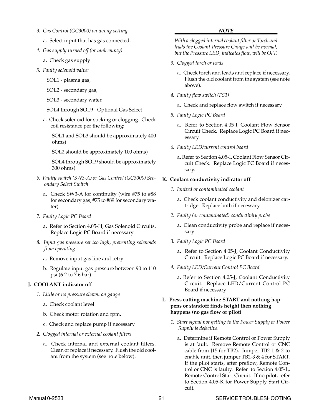
Thermal Comfort 3000 manual Coolant indicator off, Coolant conductivity indicator off

Models: 3000

1 86
Download 86 pages 31.64 Kb
Page 25
Image 25

3.Gas Control (GC3000) on wrong setting

a.Select input that has gas connected.

4.Gas supply turned off (or tank empty)

a.Check gas supply

5.Faulty solenoid valve:

SOL1 - plasma gas,

SOL2 - secondary gas,

SOL3 - secondary water,

SOL4 through SOL9 - Optional Gas Select

a.Check solenoid for sticking or clogging. Check coil resistance per the following:

SOL1 and SOL3 should be approximately 400 ohms)

SOL2 should be approximately 100 ohms)

SOL4 through SOL9 should be approximately

300ohms)

6.Faulty switch (SW3-A) or Gas Control (GC3000) Sec- ondary Select Switch

a.Check SW3-A for continuity (wire #75 to #88 for secondary gas, #75 to #89 for secondary wa- ter)

7.Faulty Logic PC Board

a.Refer to Section 4.05-H, Gas Solenoid Circuits. Replace Logic PC Board if necessary

8.Input gas pressure set too high, preventing solenoids from operating

a.Remove input gas line and retry

b.Regulate input gas pressure between 90 to 110 psi (6.2 to 7.6 bar)

J.COOLANT indicator off

1.Little or no pressure shown on gauge

a.Check coolant level

b.Check motor rotation and rpm.

c.Check and replace pump if necessary

2.Clogged internal or external coolant filters

a.Check internal and external coolant filters. Clean or replace if necessary. Flush the old cool- ant from the system (see note below).

NOTE

With a clogged internal coolant filter or Torch and leads the Coolant Pressure Gauge will be normal, but the Pressure LED, indicates flow, will be OFF.

3.Clogged torch or leads

a.Check torch and leads and replace if necessary. Flush the old coolant from the system (see note above).

4.Faulty flow switch (FS1)

a.Check and replace flow switch if necessary

5.Faulty Logic PC Board

a.Refer to Section 4.05-I, Coolant Flow Sensor Circuit Check. Replace Logic PC Board if nec- essary.

6.Faulty LED/current control board

a.Refer to Section 4.05-I, Coolant Flow Sensor Cir- cuit Check. Replace Logic PC Board if neces- sary.

K.Coolant conductivity indicator off

1.Ionized or contaminated coolant

a.Check coolant conductivity and deionizer car- tridge. Replace both if necessary

2.Faulty (or contaminated) conductivity probe

a.Clean conductivity probe and replace if neces- sary

3.Faulty Logic PC Board

a.Refer to Section 4.05-J, Coolant Conductivity Circuit. Replace Logic PC Board if necessary.

4.Faulty LED/Current Control PC Board

a.Refer to Section 4.05-J, Coolant Conductivity Circuit. Replace LED/Current Control PC Board if necessary

L.Press cutting machine START and nothing hap- pens or standoff finds height then nothing happens (no gas flow or pilot)

1.Start signal not getting to the Power Supply or Power Supply is defective.

a.Determine if Remote Control or Power Supply is at fault. Remove Remote Control or CNC cable from J15 (or TB2). Jumper TB2-1 & 2 to enable unit, then jumper TB2-3 & 4 for START. If the pilot starts, after preflow, Remote Con- trol or CNC is faulty. Refer to Section 4.05-L, Remote Control Start Circuit. If no pilot, refer to Section 4.05-K for Power Supply Start Cir- cuit.

Manual 0-2533

21

SERVICE TROUBLESHOOTING

Page 25
Image 25
Thermal Comfort 3000 manual Coolant indicator off, Coolant conductivity indicator off

3000 specifications

Thermal Comfort 3000 is an innovative solution designed to enhance indoor climate by ensuring optimal thermal comfort for users. As the demand for energy efficiency and sustainable building practices grows, Thermal Comfort 3000 emerges as a key player in providing customizable and effective climate control systems.

One of the main features of Thermal Comfort 3000 is its advanced smart technology that allows for precise temperature regulation based on real-time data. It utilizes sensors that monitor indoor and outdoor temperatures, humidity levels, and even occupancy patterns. This data is then analyzed to optimize the heating and cooling systems, ensuring that energy is used efficiently. With its ability to automatically adjust to changing conditions, users can enjoy a consistent and comfortable environment without excessive energy consumption.

Thermal Comfort 3000 is built with user convenience in mind. It comes equipped with a user-friendly interface that enables easy adjustments and programming. Through a dedicated mobile app, users can control their indoor climate remotely, providing flexibility for those with busy lifestyles. Furthermore, the system offers customizable settings that cater to individual preferences, ensuring that everyone in a space can enjoy their ideal thermal environment.

The technology behind Thermal Comfort 3000 incorporates sustainable practices, utilizing eco-friendly refrigerants and energy-efficient components. This not only reduces the carbon footprint of buildings but also lowers energy costs for users. The system can be integrated with renewable energy sources, such as solar panels, creating a truly sustainable heating and cooling solution.

Thermal Comfort 3000 also features advanced filtration systems that improve indoor air quality. By removing allergens, dust, and other pollutants from the air, it promotes a healthier living environment. This is especially beneficial for individuals with allergies or respiratory issues, making Thermal Comfort 3000 an excellent choice for homes and commercial spaces alike.

In summary, Thermal Comfort 3000 represents the future of climate control technology. Its combination of smart features, user-centric design, and sustainability makes it an ideal solution for enhancing thermal comfort in any indoor environment. With its innovative approach, it not only ensures comfort but also promotes energy efficiency and environmental responsibility, making it a worthwhile investment for modern living.