Manuals
/
Thermo Products
/
Household Appliance
/
Furnace
Thermo Products
omd-70
service manual
K. Burner Installation
Models:
omd-70
1
31
49
49
Download
49 pages
20.13 Kb
28
29
30
31
32
33
34
35
Troubleshooting
Specs
Install
Wiring Diagram
Figure J. ELECTRICAL WIRING
Maintenance
D.Filter Location And Cleaning
Safety
Power Switch
Page 31
Image 31
Page 30
Page 32
Page 31
Image 31
Page 30
Page 32
Contents
DOWN FLOW & DIRECT VENT SEALED COMBUSTION
MODEL: OMD-70 INSTALLATION AND SERVICE MANUAL
FOR YOUR SAFETY
GAS-FIREDOR OIL-FIREDFURNACE
I. SAFETY SECTION
If you do not follow these instructions exactly, a fire or explosion may result causing personal injury, loss of life or property damage
Do not attempt to start the burner when
All installations and services must be performed by qualified service personnel
POWER SWITCH
SECTION
TABLE OF CONTENTS
BEGINNING PAGE
a. Combustible material
MODELS OMD/GMD
b.Non-combustiblematerial
MODEL
III. FURNACE SPECIFICATIONS
GMD-85
BLOWER DATA
BURNER DATA
B. STANDARD CHIMNEY
IV. INSTALLATION A. ROOF JACK
C.FURNACE LOCATION
Figure 1A
D. BASE INSTALLATION
Combustible Floor Base Model: 70-BASE
Cottage Base Model: 01COT-BASE
1. Combustible Floor Base Model: 70-BASE
2. Cottage Base Model: OMCCOT-BASE
IMPORTANT: Adequate combustion air must be provided under all circumstances. If the underside of the home is skirted or enclosed e.g. by an enclosed crawlspace, the combustion air intake should exit through the side of cottage base and terminate outside of the structure. All joints and seams of supply ducts and combustion air ducts must be closed with a sealing method suitable to the application conditions and temperatures e.g. using high temperature silicone caulk and/or aluminum tape
F. CLOSET INSTALLATION
E. ALCOVE INSTALLATION
G. COMBUSTION AIR
The preferred location of the outside combustion air intake termination e.g. an optional stainless steel intake hood, part no.370183 is through the side of the structure, skirting or enclosure. An alternate termination location is under the structure in the skirted or crawlspace area providing a minimum of 50 square inches of free area exists around the perimeter for outside combustion air to be drawn through. NOTE: Combustion air cannot be drawn from the occupied space of the home
Figure
H. FUEL PIPING
2. Oil Tank and Piping OMD-70
All installations and services must be performed by qualified service personnel
Figure J. ELECTRICAL WIRING
1.Electrical Branch Supply Circuit
TERMINAL DEFINITIONS & FIELD WIRING
4. BLOWER CONTROLLER INFORMATION FOR PSC MOTOR
B. Outputs
A. Inputs
C. Operating Modes
DIAGNOSTIC FEATURES
PSC TROUBLE SHOOTING
5. WIRING DIAGRAM
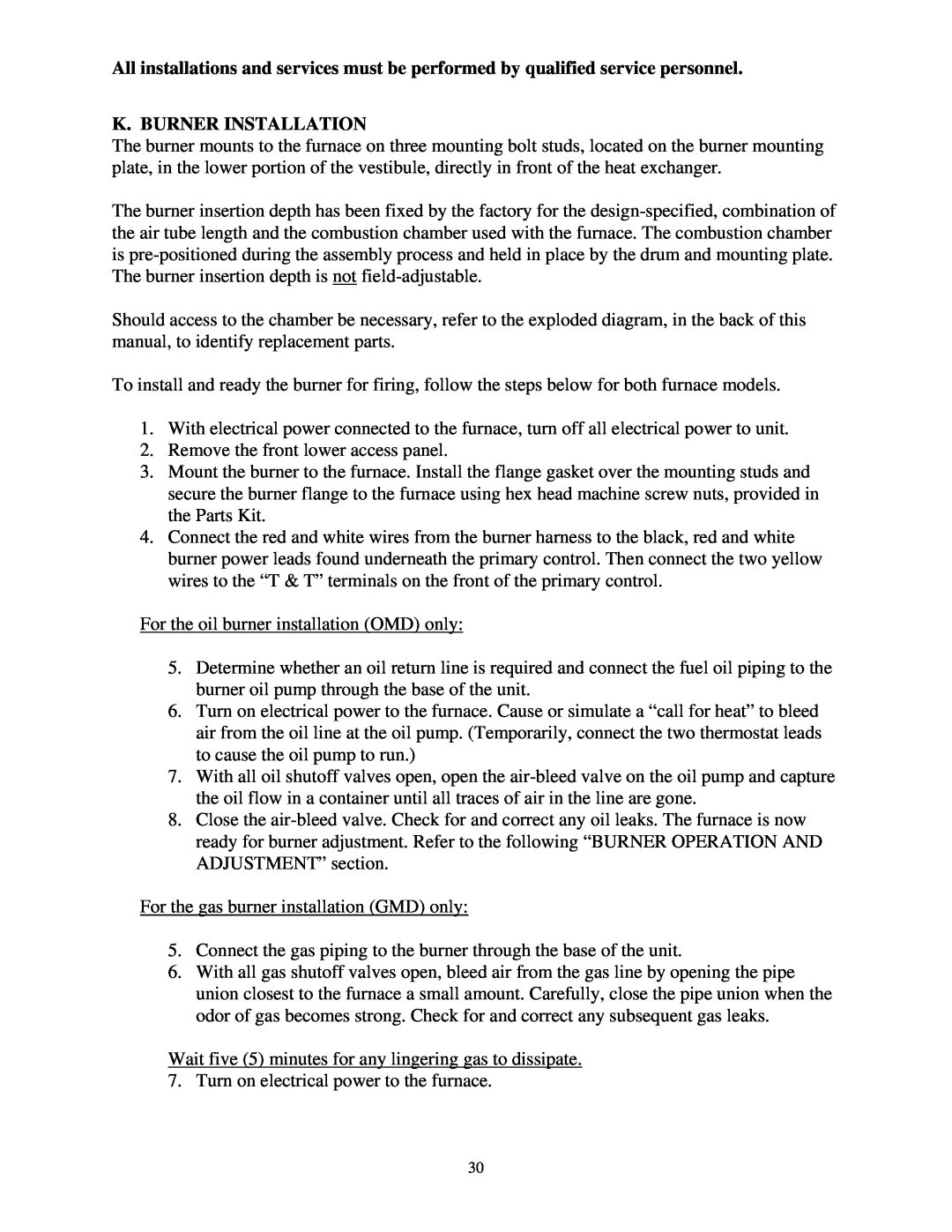
K. BURNER INSTALLATION
L.BURNER OPERATION AND ADJUSTMENT
replacement parts for location identification. After the furnace is warmed up to a steady- state condition about 15 minutes, the final burner adjustment should be made using combustion instrumentation for measuring carbon dioxide CO2 or oxygen O2, carbon monoxide CO, smoke for oil furnaces, and stack temperature. In order to achieve the most efficient combustion possible, the following steps must be taken
BURNER COMBUSTION PARAMETERS
M. FLUE GAS COMBUSTION ANALYSIS
A. TROUBLESHOOTING
V. DEALER MAINTENANCE
OMD/GMD TROUBLESHOOTING FLOWCHART
Note: Check diagnostic code through view port
prior to removing doors
Are the thermostat wires
closed? If 120 VAC is
After fuel valve opens, does the burner ignite?
Has the high limit thermostat
C.HEAT EXCHANGER CLEANING INSTRUCTIONS
B.CAD CELL CHECKOUT PROCEDURE: OMD ONLY
D. CLEANING OR REPLACING FLUE PIPES
E. EXTENDED SHUTDOWN
A. WARNINGS AND CAUTIONS
VI. USER INFORMATION SECTION
Figure C. INSPECTION AREAS
B. COMPONENT LOCATIONS
INSTALLATION / SERVICE
D.FILTER LOCATION AND CLEANING
E. CONTACT INFORMATION
APPENDIX A. REPLACEMENT PARTS LIST
Top
Page
Image
Contents