All installations and services must be performed by qualified service personnel.
B. COMPONENT LOCATIONS
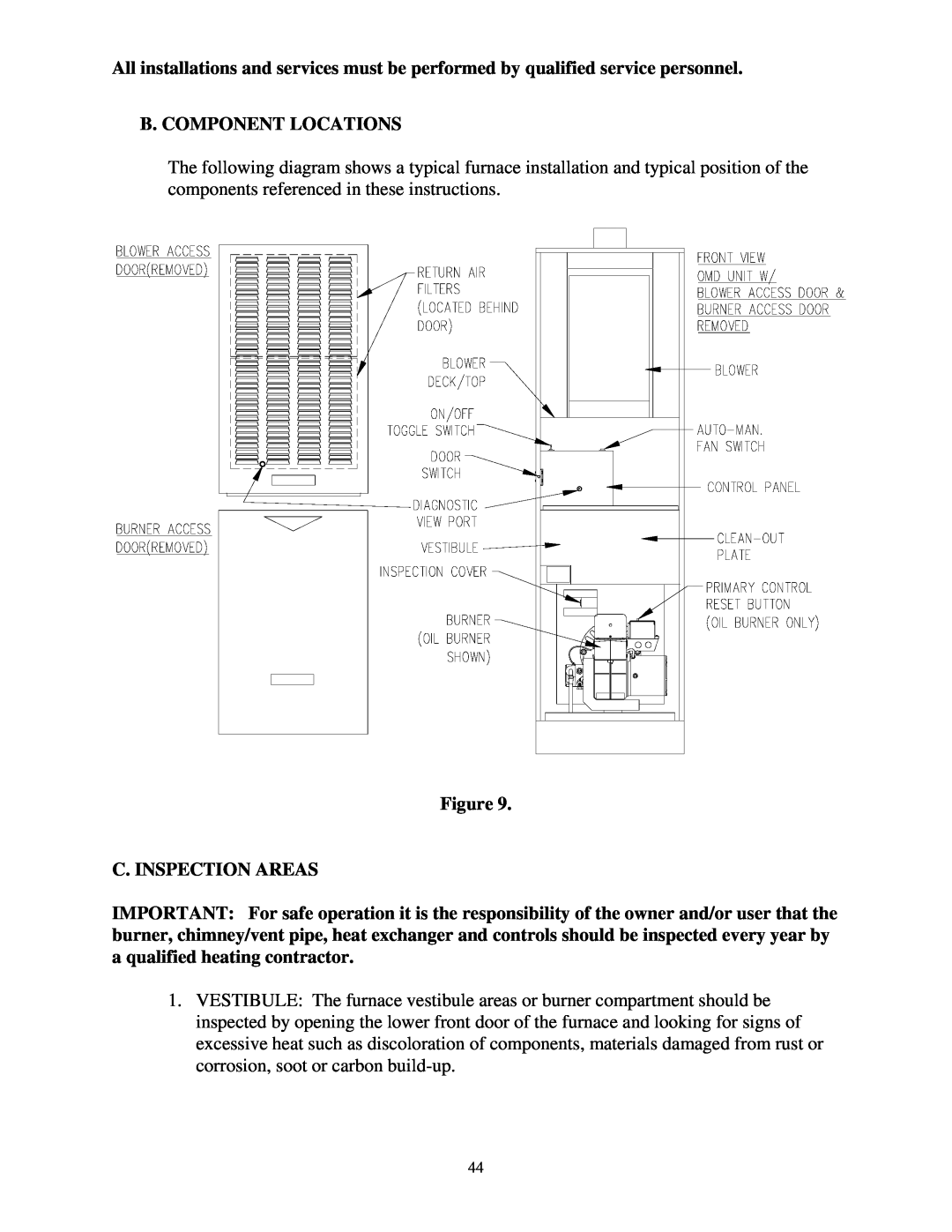
The following diagram shows a typical furnace installation and typical position of the components referenced in these instructions.
Figure 9.
C. INSPECTION AREAS
IMPORTANT: For safe operation it is the responsibility of the owner and/or user that the burner, chimney/vent pipe, heat exchanger and controls should be inspected every year by a qualified heating contractor.
1.VESTIBULE: The furnace vestibule areas or burner compartment should be inspected by opening the lower front door of the furnace and looking for signs of excessive heat such as discoloration of components, materials damaged from rust or corrosion, soot or carbon
44