All installations and services must be performed by qualified service personnel.
| DIP SWITCH 2 SECTION STATE |
|
| BLOWER DELAY TIMES | |||||||||||||||||
|
|
|
|
|
|
|
|
|
|
|
|
|
|
|
|
|
|
|
|
|
|
|
|
| 1 |
| 2 |
| 3 |
|
| 4 |
|
|
| ON - SEC | OFF - MIN | ||||||
|
|
|
|
|
|
|
|
|
|
|
|
|
|
|
|
|
|
|
|
|
|
|
|
|
| OFF |
|
| OFF |
|
|
|
|
|
|
|
| 30 |
|
|
|
| |
|
|
|
|
|
|
|
|
|
|
|
|
|
|
|
|
|
|
|
|
|
|
| FACTORY |
|
| ON |
|
| OFF |
|
|
|
|
|
|
|
|
| 60 |
|
|
|
|
| SETTING |
|
|
|
|
|
|
|
|
|
|
|
|
|
|
|
|
| |||
|
|
|
|
|
|
|
|
|
|
|
|
|
|
|
|
|
|
|
|
| |
|
|
|
| OFF |
|
| ON |
|
|
|
|
|
|
|
| 120 |
|
|
|
| |
|
|
|
|
|
|
|
|
|
|
|
|
|
|
|
|
|
|
|
|
| |
|
|
|
| ON |
|
| ON |
|
|
|
|
|
|
|
| 240 |
|
|
|
| |
|
|
|
|
|
|
|
|
|
|
|
|
|
|
|
|
| |||||
|
|
|
|
|
|
|
|
|
| OFF |
| OFF |
|
| 2 |
| |||||
|
|
|
|
|
|
|
|
|
|
|
|
|
|
|
|
|
|
|
|
|
|
| FACTORY |
|
|
|
|
|
|
|
| ON |
|
| OFF |
|
|
|
|
|
| 4 |
|
| SETTING |
|
|
|
|
|
|
|
|
|
|
|
|
|
|
|
|
| |||
|
|
|
|
|
|
|
|
|
|
|
|
|
|
|
|
|
|
|
|
| |
|
|
|
|
|
|
|
|
|
| OFF |
| ON |
|
| 6 |
| |||||
|
|
|
|
|
|
|
|
|
|
|
|
|
|
|
|
| |||||
|
|
|
|
|
|
|
|
|
| ON |
| ON |
|
| 8 |
| |||||
|
|
|
|
|
|
|
|
|
|
|
|
|
|
|
|
|
|
|
|
|
|
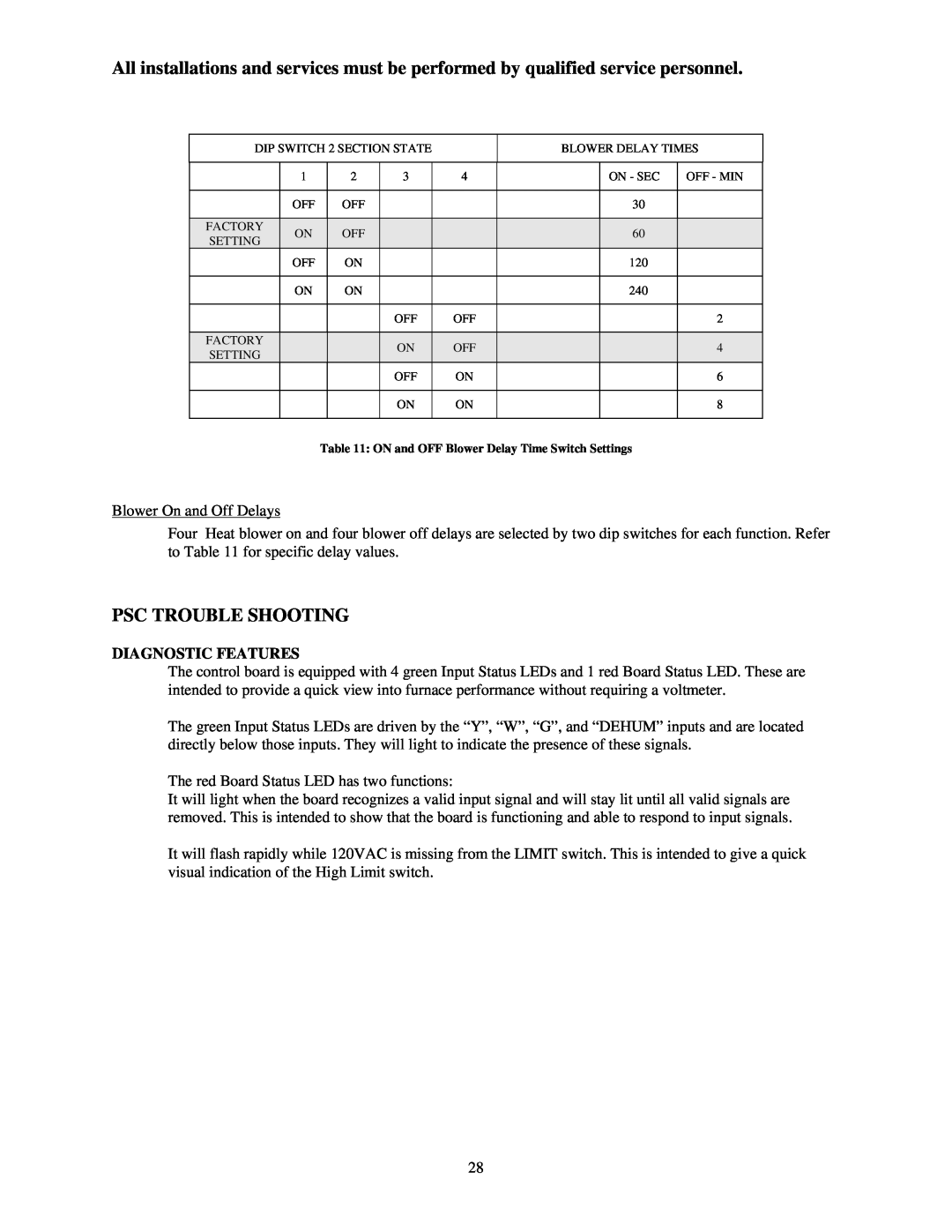
Table 11: ON and OFF Blower Delay Time Switch Settings
Blower On and Off Delays
Four Heat blower on and four blower off delays are selected by two dip switches for each function. Refer to Table 11 for specific delay values.
PSC TROUBLE SHOOTING
DIAGNOSTIC FEATURES
The control board is equipped with 4 green Input Status LEDs and 1 red Board Status LED. These are intended to provide a quick view into furnace performance without requiring a voltmeter.
The green Input Status LEDs are driven by the “Y”, “W”, “G”, and “DEHUM” inputs and are located directly below those inputs. They will light to indicate the presence of these signals.
The red Board Status LED has two functions:
It will light when the board recognizes a valid input signal and will stay lit until all valid signals are removed. This is intended to show that the board is functioning and able to respond to input signals.
It will flash rapidly while 120VAC is missing from the LIMIT switch. This is intended to give a quick visual indication of the High Limit switch.
28