Thomas & Betts FE, BE warranty Fan contd, Venter Motor, Operating Gas Valve, Fan and Limit Controls

Models: BE FE

1 28
Download 28 pages 60 Kb
Page 26
Image 26

37. Fan (cont'd)

Position the assembly on the heater. Attach the fan guard at the center mounts. (IMPORTANT: If replacing the fan guard, use the screws that held the original fan guard. These specially designed screws will cut through the coating on the fan guard to provide a ground for the fan motor.)

Rotate the fan blade to check for adequate clearance. If adjustment is required, loosen the mounting screws, re-position the fan guard, and tighten the screws. Rotate the fan blade and re-check for adequate clear- ance. Repeat this procedure until the assembly is positioned properly.

5.If necessary, drill the required upper and lower fan guard mounting holes. Attach the fan guard at all upper and lower mounting points using either the screws removed or field-installed sheet metal screws.

6.Reconnect the fan motor wires and replace the outer side panel.

7.Restore power to the heater and turn on the gas. Light, following the instructions on the lighting instruction plate. Check for proper opera- tion.

38. Venter Motor

Remove dirt and grease from the motor housing. Power venter motor is permanently lubricated.

The vent relay controls the venter motor. If the relay contacts fail to close the venter motor will not run. If the relay contacts fail to open, the venter motor will not shut off, preventing the combustion air pres- sure switch from opening.

39. Operating Gas Valve

The gas valve requires no field maintenance except careful removal of external dirt accumulation and checking of wiring connections. Instruc- tions for testing pressure settings are in Paragraph 10.

CAUTION: The operating valve is the prime safety shutoff. All gas supply lines must be free of dirt or scale before connecting to the unit to ensure positive closure. See Hazard Levels, page 2.

40. Fan and Limit Controls

If it is determined that the fan or limit control needs replacing, use only factory-authorized replacement parts that are designed for your heater.

Instructions for replacing fan or limit control:

1.Turn off the electric power and shut off the gas supply.

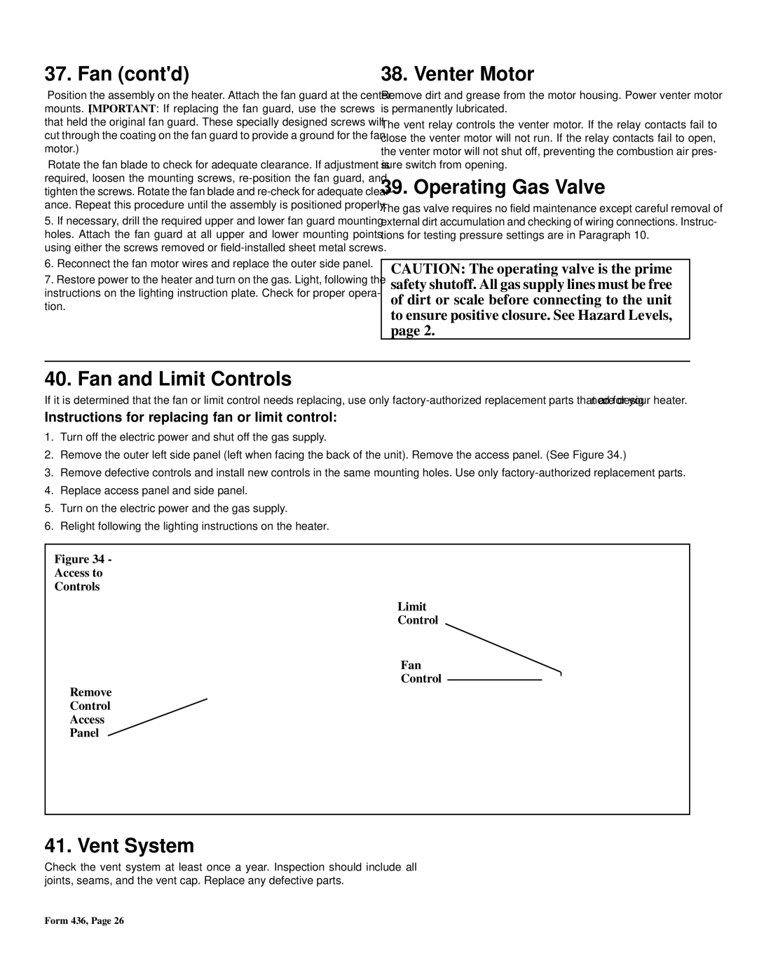
2.Remove the outer left side panel (left when facing the back of the unit). Remove the access panel. (See Figure 34.)

3.Remove defective controls and install new controls in the same mounting holes. Use only factory-authorized replacement parts.

4.Replace access panel and side panel.

5.Turn on the electric power and the gas supply.

6.Relight following the lighting instructions on the heater.

Figure 34 -

Access to

Controls

Limit

Control

Fan

Control

Remove

Control

Access

Panel

41. Vent System

Check the vent system at least once a year. Inspection should include all joints, seams, and the vent cap. Replace any defective parts.

Form 436, Page 26

Page 26
Image 26
Thomas & Betts FE, BE warranty Fan contd, Venter Motor, Operating Gas Valve, Fan and Limit Controls, Vent System

BE, FE specifications

Thomas & Betts, a subsidiary of ABB, is renowned for its innovative electrical products and solutions, particularly in the fields of connectors, terminals, and wiring devices. Among its extensive product lineup, the FE and BE series stand out for their exceptional performance and versatility in various applications.

The FE (Flat Eye) and BE (Blank Eye) connectors are designed to provide reliable electrical connections in demanding environments. These connectors are particularly well-suited for industrial, commercial, and residential applications, ensuring that they meet the rigorous standards required in these fields.

One of the key features of the FE and BE connectors is their robust construction. Made from high-quality materials, they are resistant to corrosion, moisture, and other environmental factors that could compromise the integrity of the connection. The connectors are engineered to withstand high temperatures and mechanical stress, making them ideal for use in harsh conditions where reliability is essential.

Moreover, the design of FE and BE connectors facilitates easy installation and maintenance. The connectors come with user-friendly features such as a clear labeling system and intuitive locking mechanisms, ensuring a secure fit and minimizing the risk of connection failure. Additionally, these connectors are compatible with various wire sizes, offering flexibility for different projects.

Technologically, Thomas & Betts has integrated advanced manufacturing processes to ensure precision and consistency in the production of FE and BE connectors. This attention to detail results in products that not only meet but often exceed industry standards, providing customers with peace of mind regarding their electrical systems.

In terms of performance, the FE and BE connectors deliver exceptional conductivity, which is critical for minimizing energy loss and ensuring efficient operation in electrical systems. This characteristic is especially important in applications where energy efficiency and reliability are paramount.

In summary, Thomas & Betts FE and BE connectors embody a perfect blend of durability, ease of use, and technological advancement. Their robust design, compatibility with various wire sizes, and resistance to environmental stressors make them a preferred choice for professionals in the electrical industry. With a commitment to quality and innovation, Thomas & Betts continues to set the standard in electrical connectivity solutions, ensuring that their products remain at the forefront of the industry.