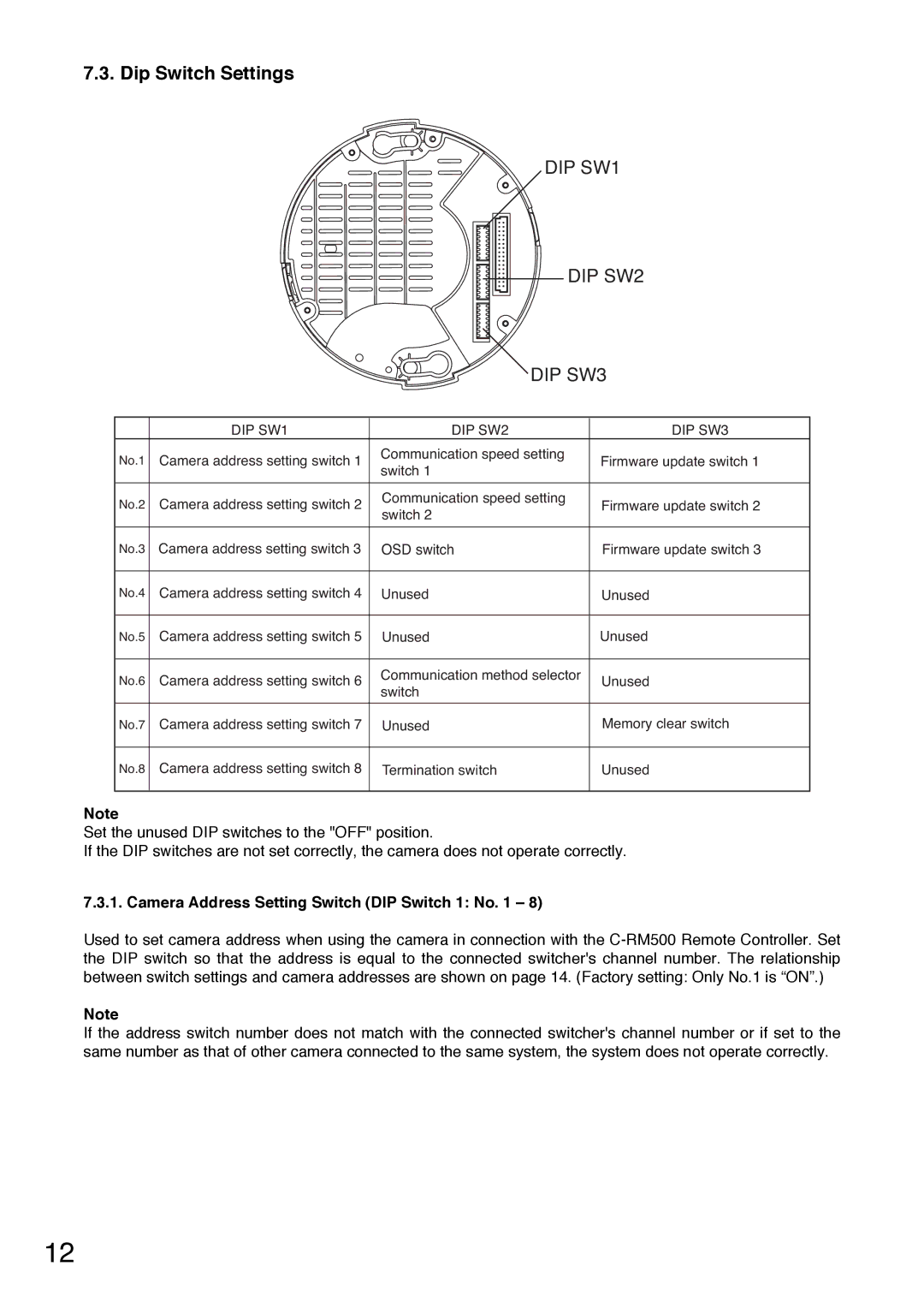
7.3. Dip Switch Settings
DIP SW1
DIP SW2
|
| DIP SW3 | ||
| DIP SW1 | DIP SW2 | DIP SW3 | |
No.1 | Camera address setting switch 1 | Communication speed setting | Firmware update switch 1 | |
switch 1 | ||||
|
|
| ||
No.2 Camera address setting switch 2 | Communication speed setting | Firmware update switch 2 | ||
switch 2 | ||||
|
|
| ||
No.3 Camera address setting switch 3 | OSD switch | Firmware update switch 3 | ||
No.4 Camera address setting switch 4 | Unused | Unused | ||
No.5 Camera address setting switch 5 | Unused | Unused | ||
No.6 Camera address setting switch 6 | Communication method selector | Unused | ||
|
| switch |
| |
No.7 Camera address setting switch 7 | Unused | Memory clear switch | ||
No.8 Camera address setting switch 8 | Termination switch | Unused | ||
Note
Set the unused DIP switches to the "OFF" position.
If the DIP switches are not set correctly, the camera does not operate correctly.
7.3.1. Camera Address Setting Switch (DIP Switch 1: No. 1 – 8)
Used to set camera address when using the camera in connection with the
Note
If the address switch number does not match with the connected switcher's channel number or if set to the same number as that of other camera connected to the same system, the system does not operate correctly.
12