Manuals
/
Toshiba
/
TV and Video
/
Satellite TV System
Toshiba
1405-S152, 1405-S151
specifications
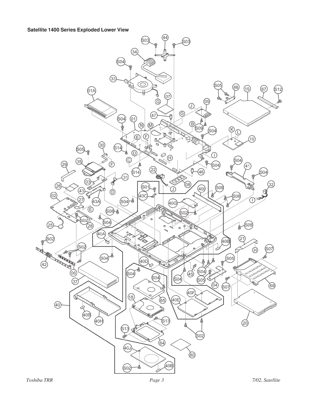
Satellite 1400 Series Exploded Lower View
Models:
1405-S152
1405-S151
1405
1
3
20
20
Download
20 pages
59.43 Kb
1
2
3
4
5
6
7
8
C1Y6 TOSH4 BAG Accessory
Weight
Page 3
Image 3
Satellite 1400 Series Exploded Lower View
Toshiba TRR
Page 3
7/02, Satellite
Page 2
Page 4
Page 3
Image 3
Page 2
Page 4
Contents
PS140U-027XF3
Weight
1400-S151 1400-S152 PS140U-027XF7
1405-S151 1405-S152 PS140U-027XFX
Satellite 1400 Series Exploded Upper View
Satellite 1400 Series Exploded Lower View
Satellite 1400 Series Part Numbers
Ref. # Code Description
Comments
Ref. # Code Description PIR Comments
Satellite 1400 Series Part Numbers,
Hexa Stud
C1Y6 TOSH4 BAG Accessory
CPU Holder
CPU Stud
Satellite 1400 Series Disassembly Overview
Remove one M2.5x4 black flat-head screw
Satellite 1400 Series Disassembly Overview,
Remove two M2x4 super flat screws securing the MDC
Thirteen M2.5x6 black flat-head Six M2.5x5 black flat-head
Remove two M2.5x2.6 black flat-head screws
Remove two M2.5x6 black screws and two M2.5x16 black screws
To remove the optical disk drive, follow the steps below
Disconnect the touch pad Sumi card from CN1 on the touch pad
Lift out the HDD connector board
Remove the CD switch board from the front cover assembly
One M2.5x6 One M2.5x14
Satellite 1400 Series Disassembly Overview,
To remove the CPU, follow the steps below
Images on the next
Remove one M2.5x6 tapping screw securing the metal brace
Remove two M2.5x6 tapping screws securing the metal plate
Interrupt Level Assigned to
Satellite 1400 Series Interrupts / Memory Map
Satellite 1400 Series Input/Output Port Assignments
Port address Device/function
VGA
Top
Page
Image
Contents