Satellite 1400 Series Disassembly Overview, cont.
"
#
!
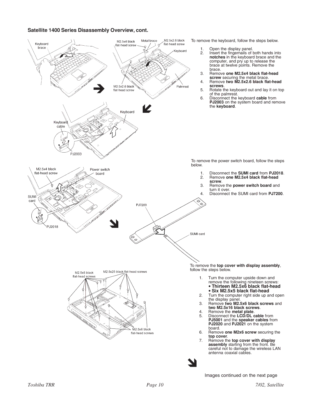
To remove the keyboard, follow the steps below.
1.Open the display panel.
2.Insert the fingernails of both hands into notches in the keyboard brace and the computer, and pry up to release the brace at twelve points. Remove the brace.
3.Remove one M2.5x4 black
4.Remove two M2.5x2.6 black flat-head screws.
5.Rotate the keyboard out and lay it on top of the palmrest.
6.Disconnect the keyboard cable from PJ2003 on the system board and remove the keyboard.
To remove the power switch board, follow the steps below.
1.Disconnect the SUMI card from PJ2018.
2.Remove one M2.5x4 black
3.Remove the power switch board and turn it over.
4.Disconnect the SUMI card from PJ7200.
To remove the top cover with display assembly, follow the steps below.
1.Turn the computer upside down and remove the following nineteen screws:
•Thirteen M2.5x6 black flat-head
•Six M2.5x5 black flat-head
2.Turn the computer right side up and open the display panel.
3.Remove two M2.5x6 black screws and two M2.5x16 black screws.
4.Remove the metal plate.
5.Disconnect the LCD/DL cable from PJ5001 and the speaker cables from PJ2020 and PJ2021 on the system board.
6.Remove one M2x6 screw securing the top cover.
7.Remove the top cover with display assembly starting from the front. Be careful not to damage the wireless LAN antenna coaxial cables.
!
Images continued on the next page
Toshiba TRR | Page 10 | 7/02, Satellite |