SPECIFIC INFORMATIONS GENERAL ADJUSTMENTS
ITEM |
| ADJUSTMENT PROCEDURE | ||||||||||||||||
|
|
|
|
|
|
|
|
|
|
|
|
|
|
|
|
|
|
|
HEIGHT | 1. | Call up the adjustment mode display, then select the item HIT. | ||||||||||||||||
(HIT) | 2. | Press the VOLUME s or t button to get the picture so the top of raster begins | ||||||||||||||||
|
| to lack. | ||||||||||||||||
| 3. Press the VOLUME s button to advance the data by 10 steps. | |||||||||||||||||
| Note : Check the vertical picture position is correct. | |||||||||||||||||
|
|
| ||||||||||||||||
WIDTH | 1. | Call up the adjustment mode display, then select the item WID. | ||||||||||||||||
(WID) | 2. | Press the VOLUME s or t button to get the picture so the left and right edges | ||||||||||||||||
|
| of raster begins to lack. | ||||||||||||||||
| 3. Press the VOLUME s or t button to advance the data by 10 steps. | |||||||||||||||||
|
| Note : Check the horizontal picture position is correct. | ||||||||||||||||
|
|
| ||||||||||||||||
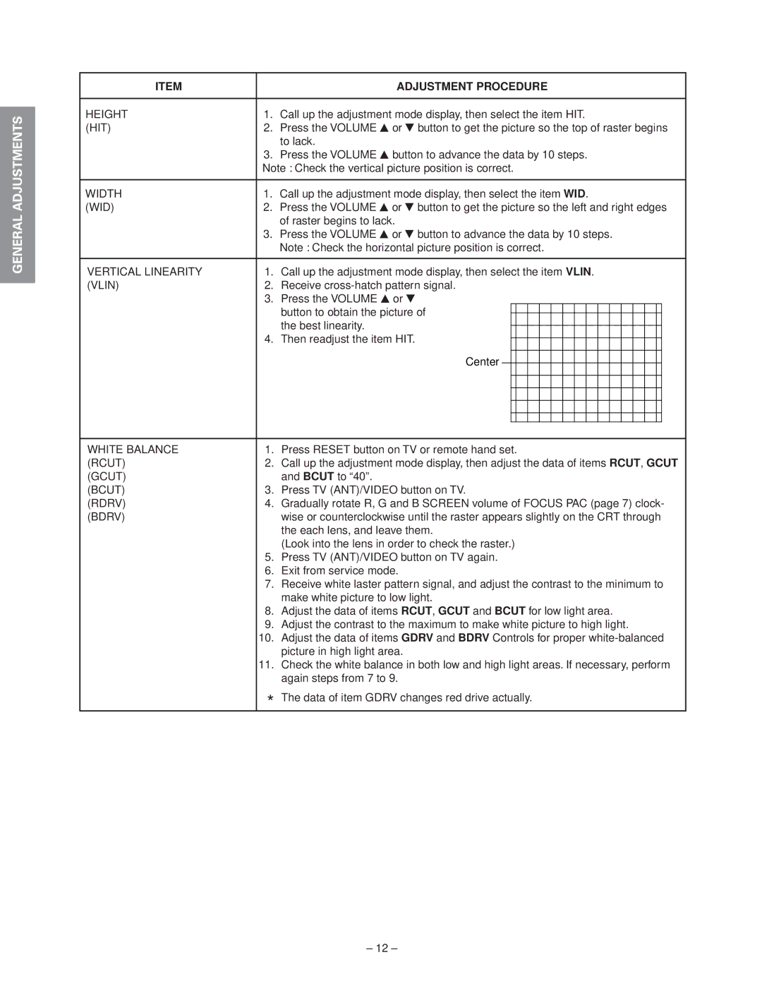
VERTICAL LINEARITY | 1. | Call up the adjustment mode display, then select the item VLIN. | ||||||||||||||||
(VLIN) | 2. | Receive | ||||||||||||||||
| 3. Press the VOLUME s or t | |||||||||||||||||
|
| button to obtain the picture of |
|
|
|
|
|
|
|
|
|
|
|
|
|
|
| |
|
|
|
|
|
|
|
|
|
|
|
|
|
|
|
|
| ||
|
| the best linearity. |
|
|
|
|
|
|
|
|
|
|
|
|
|
|
| |
|
|
|
|
|
|
|
|
|
|
|
|
|
|
|
|
| ||
| 4. Then readjust the item HIT. |
|
|
|
|
|
|
|
|
|
|
|
|
|
|
| ||
|
|
|
|
|
|
|
|
|
|
|
|
|
|
|
| |||
|
| Center |
|
|
|
|
|
|
|
|
|
|
|
|
|
|
|
|
|
|
|
|
|
|
|
|
|
|
|
|
|
|
|
|
|
| |
|
|
|
|
|
|
|
|
|
|
|
|
|
|
|
|
|
| |
|
|
|
|
|
|
|
|
|
|
|
|
|
|
|
|
|
|
|
|
|
|
|
|
|
|
|
|
|
|
|
|
|
|
|
|
|
|
|
|
|
|
|
|
|
|
|
|
|
|
|
|
|
|
|
|
|
|
|
|
|
|
|
|
|
|
|
|
|
|
|
|
|
|
|
|
|
|
|
|
|
|
|
|
|
|
|
|
|
|
|
|
|
|
|
|
|
| ||||||||||||||||
WHITE BALANCE | 1. | Press RESET button on TV or remote hand set. | ||||||||||||||||
(RCUT) | 2. | Call up the adjustment mode display, then adjust the data of items RCUT, GCUT | ||||||||||||||||
(GCUT) |
| and BCUT to “40”. | ||||||||||||||||
(BCUT) | 3. | Press TV (ANT)/VIDEO button on TV. | ||||||||||||||||
(RDRV) | 4. | Gradually rotate R, G and B SCREEN volume of FOCUS PAC (page 7) clock- | ||||||||||||||||
(BDRV) |
| wise or counterclockwise until the raster appears slightly on the CRT through | ||||||||||||||||
|
| the each lens, and leave them. | ||||||||||||||||
|
| (Look into the lens in order to check the raster.) | ||||||||||||||||
| 5. | Press TV (ANT)/VIDEO button on TV again. | ||||||||||||||||
| 6. | Exit from service mode. | ||||||||||||||||
| 7. | Receive white laster pattern signal, and adjust the contrast to the minimum to | ||||||||||||||||
|
| make white picture to low light. | ||||||||||||||||
| 8. | Adjust the data of items RCUT, GCUT and BCUT for low light area. | ||||||||||||||||
| 9. | Adjust the contrast to the maximum to make white picture to high light. | ||||||||||||||||
| 10. | Adjust the data of items GDRV and BDRV Controls for proper | ||||||||||||||||
|
| picture in high light area. | ||||||||||||||||
| 11. | Check the white balance in both low and high light areas. If necessary, perform | ||||||||||||||||
|
| again steps from 7 to 9. | ||||||||||||||||
| * The data of item GDRV changes red drive actually. | |||||||||||||||||
– 12 –
