ELECTRICAL ADJUSTMENT
ITEM |
|
| ADJUSTMENT PROCEDURE | |||||||||
|
|
|
|
|
|
|
|
|
|
|
|
|
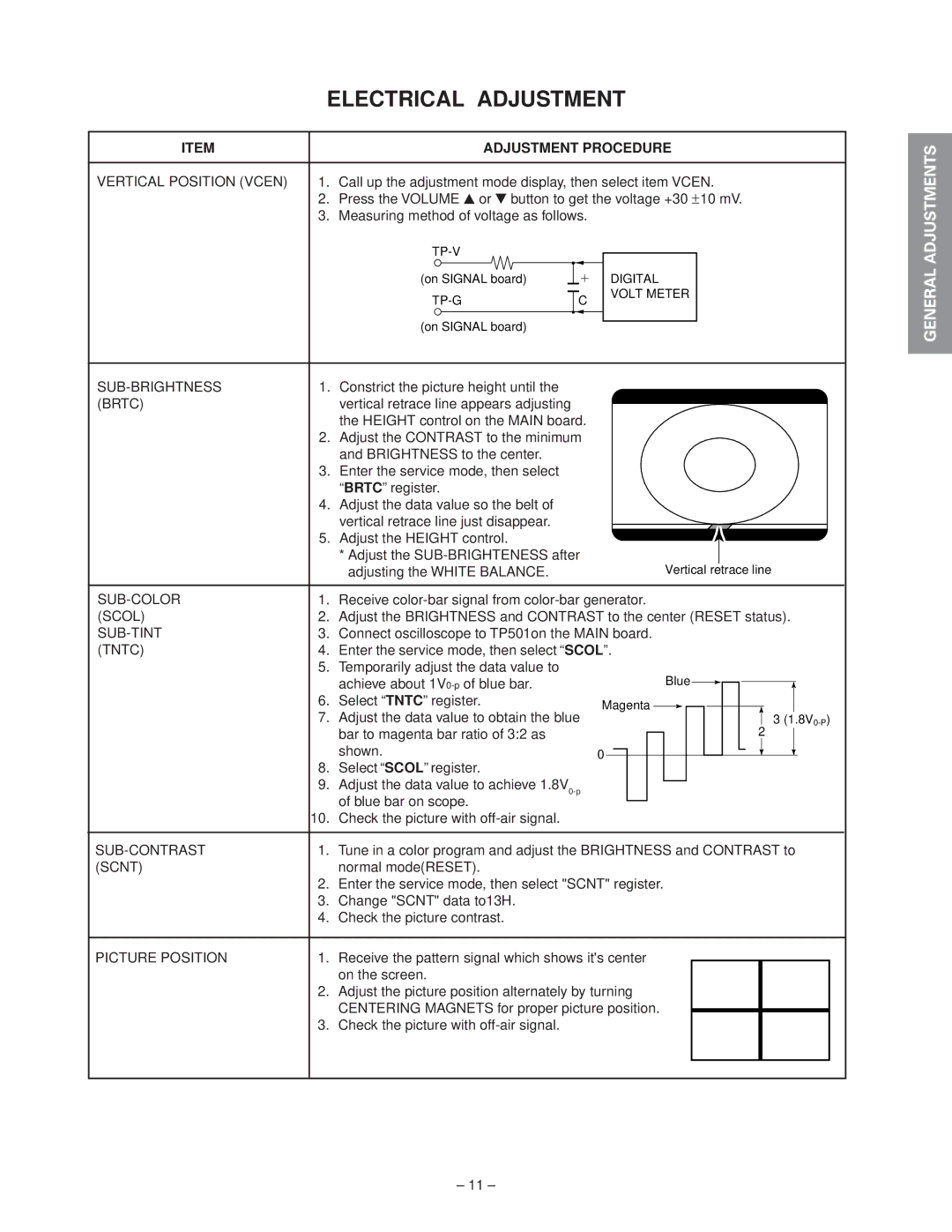
VERTICAL POSITION (VCEN) | 1. | Call up the adjustment mode display, then select item VCEN. | ||||||||||
| 2. Press the VOLUME s or t button to get the voltage +30 ±10 mV. | |||||||||||
| 3. Measuring method of voltage as follows. |
|
|
| ||||||||
|
|
|
|
|
|
|
|
|
| |||
|
| (on SIGNAL board) |
|
|
|
|
|
| DIGITAL |
| ||
|
|
|
|
|
|
|
|
|
| VOLT METER |
|
|
|
| C |
|
| ||||||||
|
|
|
|
| ||||||||
|
|
|
|
|
|
|
|
|
|
|
|
|
|
| (on SIGNAL board) |
|
|
|
|
|
|
|
| ||
|
|
|
|
|
|
|
|
|
| |||
|
|
|
|
|
|
|
|
|
|
|
|
|
1. | Constrict the picture height until the |
|
|
|
|
|
|
|
| |||
(BRTC) |
| vertical retrace line appears adjusting |
|
|
|
|
|
|
|
| ||
|
| the HEIGHT control on the MAIN board. |
|
|
| |||||||
| 2. | Adjust the CONTRAST to the minimum |
|
|
| |||||||
|
| and BRIGHTNESS to the center. |
|
|
|
|
|
|
|
| ||
| 3. | Enter the service mode, then select |
|
|
|
|
|
|
|
| ||
|
| “BRTC” register. |
|
|
|
|
|
|
|
| ||
| 4. | Adjust the data value so the belt of |
|
|
|
|
|
|
|
| ||
|
| vertical retrace line just disappear. |
|
|
|
|
|
|
|
| ||
| 5. Adjust the HEIGHT control. |
|
|
|
|
|
|
|
|
|
|
|
|
|
|
|
|
|
|
|
|
|
|
|
|
| |
|
|
|
|
|
|
|
|
|
|
|
|
|
|
|
|
|
|
|
|
|
|
|
|
|
| ||
|
| * Adjust the |
|
|
|
|
|
| Vertical |
| retrace line | ||||||||||||||||
|
| adjusting the WHITE BALANCE. |
|
|
|
|
|
|
| ||||||||||||||||||
|
|
|
|
|
|
|
|
|
|
|
|
|
|
|
|
|
|
|
|
|
|
|
|
| |||
1. | Receive | ||||||||||||||||||||||||||
(SCOL) | 2. | Adjust the BRIGHTNESS and CONTRAST to the center (RESET status). | |||||||||||||||||||||||||
3. | Connect oscilloscope to TP501on the MAIN board. | ||||||||||||||||||||||||||
(TNTC) | 4. | Enter the service mode, then select “SCOL”. | |||||||||||||||||||||||||
| 5. | Temporarily adjust the data value to |
|
|
|
|
|
| Blue |
|
|
|
|
|
|
|
|
|
|
|
|
|
|
|
| ||
|
| achieve about |
|
|
|
|
|
|
|
|
|
|
|
|
|
|
|
|
|
| |||||||
| 6. | Select “TNTC” register. | Magenta |
|
|
|
|
|
|
|
|
|
|
|
|
|
|
|
|
|
|
|
| ||||
| 7. | Adjust the data value to obtain the blue |
|
|
|
|
|
|
|
|
|
|
|
|
|
|
|
|
|
|
|
|
| 3 ( | |||
|
|
|
|
|
|
|
|
|
|
|
|
|
|
|
|
|
|
|
| 2 | |||||||
|
| bar to magenta bar ratio of 3:2 as |
|
|
|
|
|
|
|
|
|
|
|
|
|
|
|
|
|
|
|
|
| ||||
|
|
|
|
|
|
|
|
|
|
|
|
|
|
|
|
|
| ||||||||||
|
|
|
|
|
|
|
|
|
|
|
|
|
|
|
|
|
|
|
|
|
|
|
|
| |||
|
| shown. | 0 |
|
|
|
|
|
|
|
|
|
|
|
|
|
|
|
|
|
|
|
|
|
|
|
|
|
|
|
|
|
|
|
|
|
|
|
|
|
|
|
|
|
|
|
|
|
|
|
|
|
| ||
|
|
|
|
|
|
|
|
|
|
|
|
|
|
|
|
|
|
|
|
|
|
|
|
|
| ||
8.Select “SCOL” register.
9.Adjust the data value to achieve
10.Check the picture with
1. | Tune in a color program and adjust the BRIGHTNESS and CONTRAST to |
| |||
(SCNT) |
| normal mode(RESET). |
| ||
| 2. | Enter the service mode, then select "SCNT" register. |
| ||
| 3. | Change "SCNT" data to13H. |
| ||
| 4. | Check the picture contrast. |
| ||
|
|
|
|
|
|
PICTURE POSITION | 1. | Receive the pattern signal which shows it's center |
|
|
|
|
| on the screen. |
|
|
|
| 2. | Adjust the picture position alternately by turning |
|
|
|
|
| CENTERING MAGNETS for proper picture position. |
|
|
|
|
|
|
|
| |
| 3. | Check the picture with |
|
|
|
|
|
|
|
|
|
SPECIFIC INFORMATIONS GENERAL ADJUSTMENTS
– 11 –