INTRODUCTION
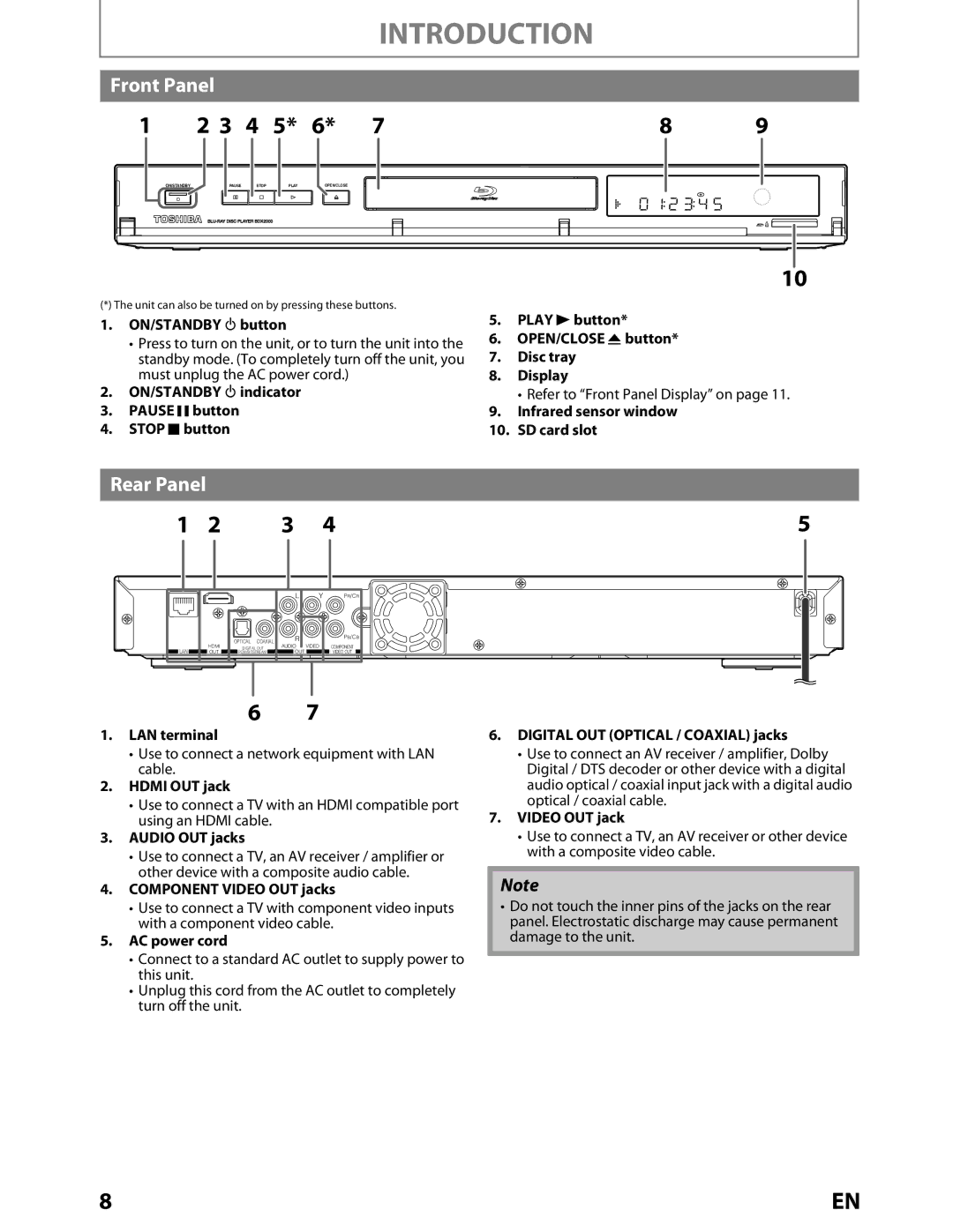
Front Panel
1 | 2 3 | 4 | 5* | 6* | 7 | 8 | 9 |
ON/STANDBY
PAUSE | STOP |
PLAY | OPEN/CLOSE |
10 |
(*) The unit can also be turned on by pressing these buttons.
1.ON/STANDBY Qbutton
•Press to turn on the unit, or to turn the unit into the standby mode. (To completely turn off the unit, you must unplug the AC power cord.)
2.ON/STANDBY Qindicator
3.PAUSE F button
4.STOP C button
5.PLAY B button*
6.OPEN/CLOSE A button*
7.Disc tray
8.Display
• Refer to “Front Panel Display” on page 11.
9.Infrared sensor window
10.SD card slot
Rear Panel
1 | 2 | 3 | 4 | 5 |
L | Y | PR/CR |
|
| OPTICAL COAXIAL | R |
LAN | HDMI | DIGITAL OUT | AUDIO VIDEO |
OUT | PCM/BITSTREAM | OUT |
PB/CB
COMPONENT
VIDEO OUT
67
1.LAN terminal
•Use to connect a network equipment with LAN cable.
2.HDMI OUT jack
•Use to connect a TV with an HDMI compatible port using an HDMI cable.
3.AUDIO OUT jacks
•Use to connect a TV, an AV receiver / amplifier or other device with a composite audio cable.
4.COMPONENT VIDEO OUT jacks
•Use to connect a TV with component video inputs with a component video cable.
5.AC power cord
•Connect to a standard AC outlet to supply power to this unit.
•Unplug this cord from the AC outlet to completely turn off the unit.
6.DIGITAL OUT (OPTICAL / COAXIAL) jacks
•Use to connect an AV receiver / amplifier, Dolby Digital / DTS decoder or other device with a digital audio optical / coaxial input jack with a digital audio optical / coaxial cable.
7.VIDEO OUT jack
•Use to connect a TV, an AV receiver or other device with a composite video cable.
Note
•Do not touch the inner pins of the jacks on the rear panel. Electrostatic discharge may cause permanent damage to the unit.
8 | EN |