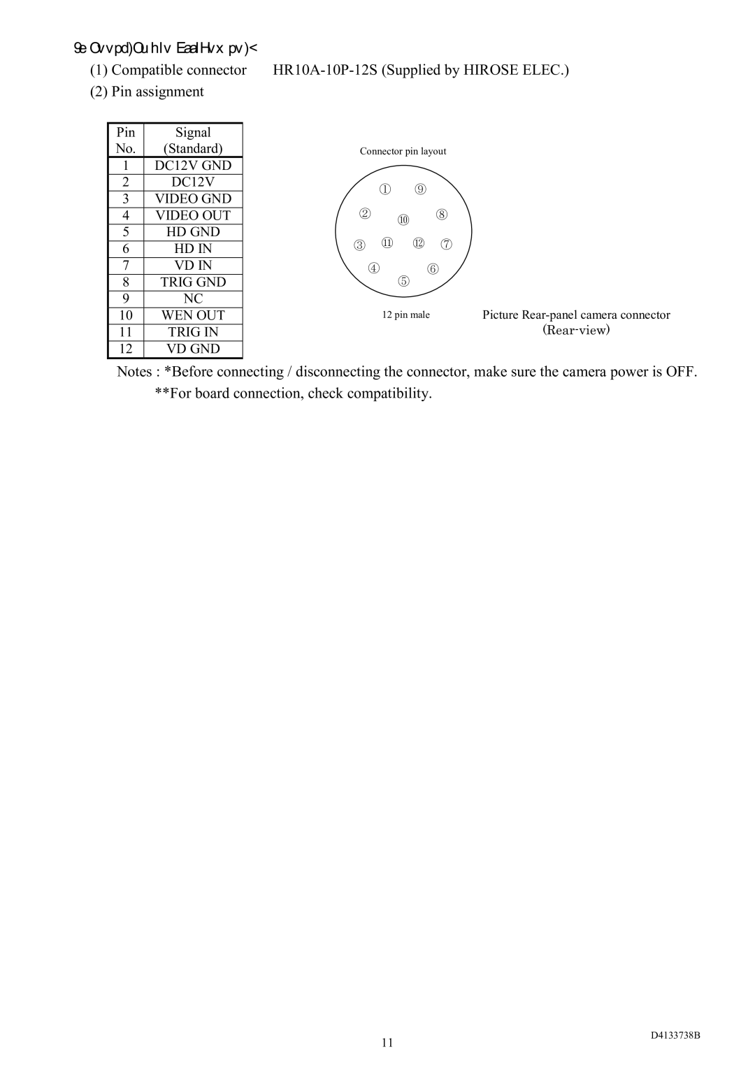
[Connector pin assignment] |
|
|
| |||
(1) Compatible connector | ||||||
(2) Pin assignment |
|
|
| |||
|
|
|
|
|
|
|
| Pin | Signal |
|
|
|
|
| No. | (Standard) |
| Connector pin layout | ||
| 1 | DC12V GND |
|
|
|
|
| 2 | DC12V |
| ① | ⑨ |
|
|
|
|
|
| ||
| 3 | VIDEO GND |
|
| ||
|
|
|
|
| ||
| 4 | VIDEO OUT |
| ② | ⑩ | ⑧ |
| 5 | HD GND |
| ③ ⑪ | ⑫ | ⑦ |
| 6 | HD IN |
| |||
|
|
|
|
| ||
|
|
|
|
|
| |
| 7 | VD IN |
| ④ | ⑥ | |
| 8 | TRIG GND |
|
| ⑤ |
|
| 9 | NC |
|
|
|
|
|
|
|
|
|
| |
| 10 | WEN OUT |
| 12 pin male | Picture | |
| 11 | TRIG IN |
|
|
| |
|
|
|
|
|
|
|
| 12 | VD GND |
|
|
|
|
Notes : *Before connecting / disconnecting the connector, make sure the camera power is OFF. **For board connection, check compatibility.
11
D4133738B
