7. 5 EXT TRIG (External trigger)
Charge begins to accumulate after the trigger input, and 1 frame images are output. There are five modes: 1P SNR, 1P SR, PW SNR, PW SR, RR.
The RGB terminal trigger input and index output interface are as shown below.
5V
15kΩ 1SS357
Trigger input
150Ω
(CMOS out)
INDEX out
( 1 ) 1P SNR (1 Pulse Sync Non Reset)
Charge begins to accumulate after the trigger input to the RGB terminal, and 1 field images are output.
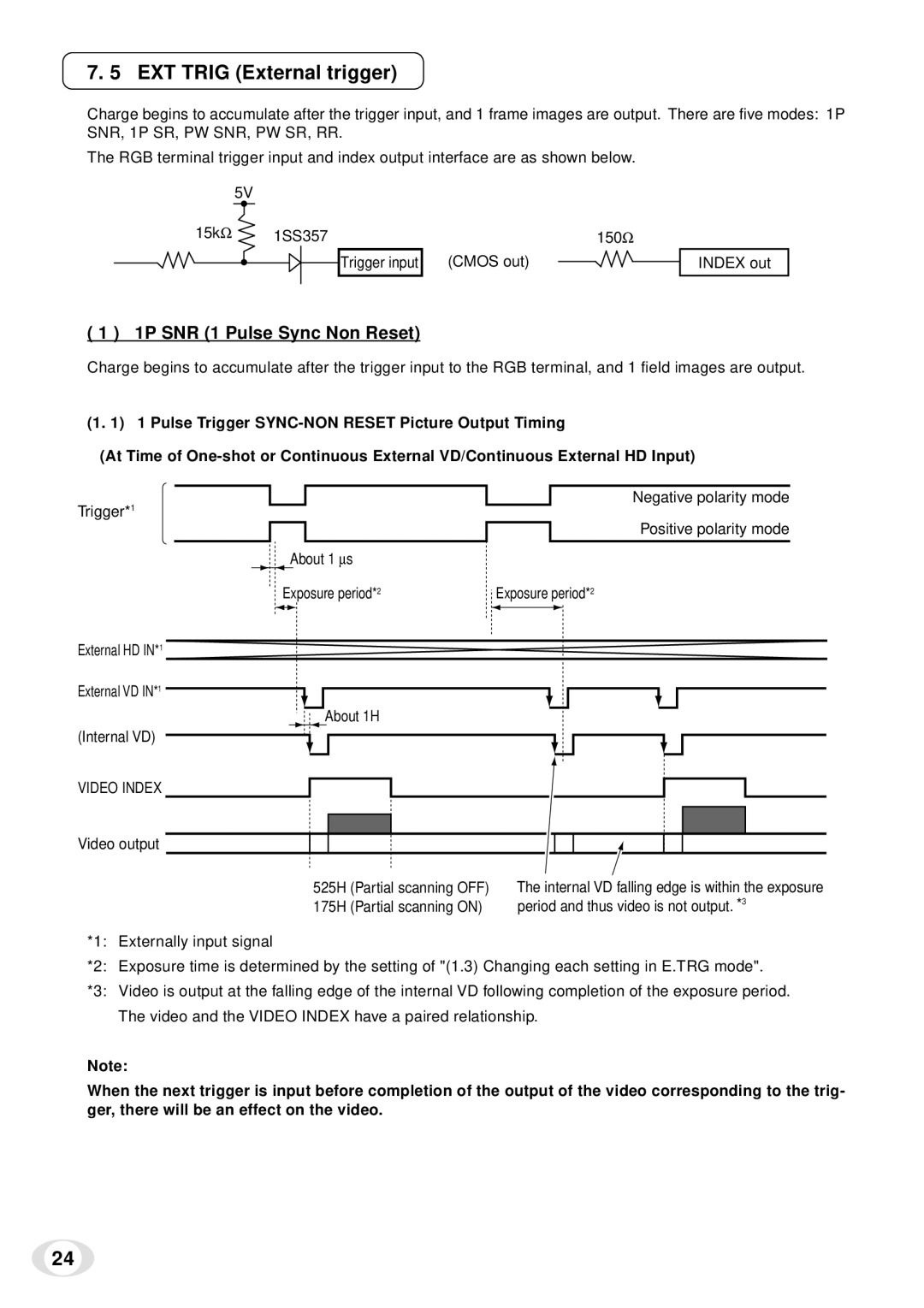
(1. 1) 1 Pulse Trigger
(At Time of
Trigger*1
External HD IN*1
External VD IN*1
(Internal VD)
VIDEO INDEX
Video output
Negative polarity mode
Positive polarity mode
About 1 ∝ s
| Exposure period*2 | Exposure period*2 | ||||||||
|
|
|
|
|
|
|
|
|
|
|
|
|
|
|
|
|
|
|
|
|
|
|
|
|
|
|
|
|
|
|
|
|
|
|
|
|
|
|
|
|
|
|
|
|
|
|
|
|
|
|
|
|
|
|
|
|
|
|
|
|
|
|
|
|
|
About 1H
525H | (Partial scanning OFF) | The internal VD falling edge is within the exposure |
175H | (Partial scanning ON) | period and thus video is not output. *3 |
*1: Externally input signal
*2: Exposure time is determined by the setting of "(1.3) Changing each setting in E.TRG mode".
*3: Video is output at the falling edge of the internal VD following completion of the exposure period. The video and the VIDEO INDEX have a paired relationship.
Note:
When the next trigger is input before completion of the output of the video corresponding to the trig- ger, there will be an effect on the video.
24