5.CONNECTION
5.1 Standard Connection
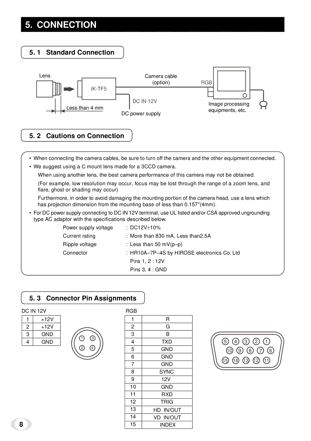
Lens
Less than 4 mm
Camera cable |
|
(option) | RGB |
DC IN 12V | Image processing |
| |
DC power supply | equipments, etc. |
|
5. 2 Cautions on Connection
•When connecting the camera cables, be sure to turn off the camera and the other equipment connected.
•We suggest using a C mount lens made for a 3CCD camera.
When using another lens, the best camera performance of this camera may not be obtained.
(For example, low resolution may occur, focus may be lost through the range of a zoom lens, and flare, ghost or shading may occur)
Furthermore, in order to avoid damaging the mounting portion of the camera head, use a lens which has projection dimension from the mounting base of less than 0.157"(4mm).
•For DC power supply connecting to DC IN 12V terminal, use UL listed and/or CSA approved ungrounding type AC adaptor with the specifications described below.
Power supply voltage | : DC12V± 10% | |
Current rating | : More than 830 mA, Less than2.5A | |
Ripple voltage | : Less than 50 | |
Connector | : | |
| Pins 1, 2 | : 12V |
| Pins 3, 4 | : GND |
5. 3 Connector Pin Assignments
DC IN 12V
1+12V
2+12V
3GND
4GND
8
|
| RGB |
|
|
|
|
|
| |
|
| 1 | R |
|
|
|
|
| |
|
| 2 | G |
|
|
|
|
| |
1 | 3 | 3 | B |
|
|
|
|
| |
4 | TXD | 5 | 4 | 3 | 2 | 1 | |||
|
| ||||||||
2 | 4 | 5 | GND | 10 | 9 |
| 8 | 7 6 | |
|
|
| |||||||
|
| 6 | GND | 15 | 14 | 13 | 12 | 11 | |
|
| 7 | GND | ||||||
|
|
|
|
|
|
| |||
|
| 8 | SYNC |
|
|
|
|
| |
|
| 9 | 12V |
|
|
|
|
| |
|
| 10 | GND |
|
|
|
|
| |
|
| 11 | RXD |
|
|
|
|
| |
|
| 12 | TRIG |
|
|
|
|
| |
|
| 13 | HD IN/OUT |
|
|
|
|
| |
|
| 14 | VD IN/OUT |
|
|
|
|
| |
|
| 15 | INDEX |
|
|
|
|
|