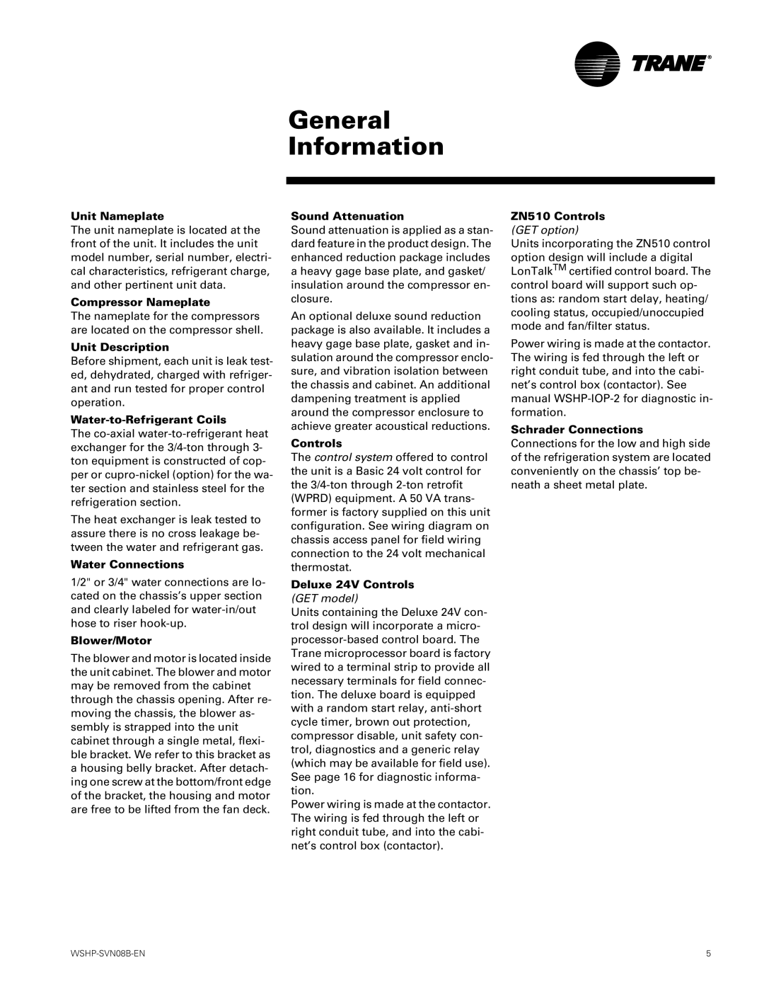
GETB specifications
The Trane GETB, known for its exceptional efficiency and reliability, stands as a leader in the commercial HVAC industry. Designed to meet the demands of varying environments, the GETB system is particularly beneficial for buildings requiring constant heating and cooling performance.One of the standout features of the GETB is its use of the Trane Tracer SC+ building management system. This intelligent control platform allows facility managers to efficiently monitor and manage HVAC settings remotely, optimizing comfort and energy consumption. The integration of smart technology significantly reduces operational costs by promoting energy-saving strategies tailored to specific building requirements.
A notable technology incorporated in the Trane GETB system is the use of advanced variable-speed compressors. These compressors adjust their output based on the needs of the building, providing precise temperature control and minimizing energy wastage. With this technology, the GETB can achieve high efficiencies across various load conditions, which is particularly advantageous during periods of fluctuating occupancy.
Another important characteristic of the GETB is its robust design tailored for durability and longevity. Constructed with high-quality materials and components, the system is engineered to withstand the rigors of continuous operation in industrial environments. This resilience ensures minimal disruptions and maintenance needs, allowing for a seamless integration into any facility.
Additionally, the GETB offers extensive options for zoning and temperature control. With its zoning capabilities, different areas of a building can be maintained at separate temperature settings, enhancing comfort for occupants while contributing to energy conservation. The ability to customize the system to suit specific building layouts makes the GETB a versatile choice for a variety of applications.
Furthermore, the GETB is designed with environmental sustainability in mind. By using refrigerants with lower global warming potential, Trane has focused on reducing the ecological footprint of its products. This commitment to sustainability does not only comply with regulatory standards but also supports building owners looking to achieve green certifications.
In summary, the Trane GETB combines advanced technologies, robust design, and energy-efficient features to provide a dependable HVAC solution for commercial spaces. With its smart controls, variable-speed compressors, and emphasis on sustainability, it represents an ideal choice for those seeking reliable heating and cooling in a dynamic and eco-conscious manner.

