Manuals
/
Trane
/
Household Appliance
/
Air Conditioner
Trane
SCRH, SCWH Isolator Placement, pre-installation Installation considerations, 1 7/8, 3 3/4
Models:
SCWH
SCRH
1
9
36
36
Download
36 pages
54.67 Kb
6
7
8
9
10
11
12
13
Troubleshooting
Install
Unit Wiring Diagrams
Ground Wire
Dimension
Maintenance
Proper Lifting Procedure
Checklist
Cleaning the Condenser Coils
Weight
Page 9
Image 9
Page 8
Page 10
Page 9
Image 9
Page 8
Page 10
Contents
October
“AO” and later design sequence
Installation, Operation, and Maintenance
Midrange Self-ContainedUnits
Warnings and Cautions
general information
Example Warnings and Cautions
Special Note on Refrigeration Emissions
Installation…………………………………………………2
contents
Maintenance ……………………………………………25
Operation…………………………………………………24
Unit Airflow Configurations
Installation information
general
Midrange Model Number Description
general
Refrigerant Handling Procedures
General
Installation information
Installation Preparation
pre-installation Installation considerations
Receiving and Handling
Pre-InstallationConsiderations
Service Access
pre-installation Installation considerations
3 through 7.5-tonSCRH/SCWH
pre-installation Installation considerations
Service Access
10 through 15-tonSCRH/SCWH
pre-installation Installation considerations
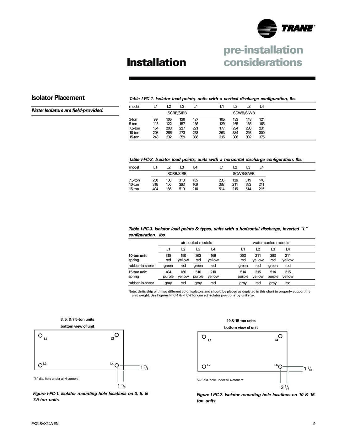
Isolator Placement
Note Isolators are field-provided
1 7/8
Proper Lifting Procedure
pre-installation Installation considerations
Improper Unit Lift
Installation weights
dimensions &
3 & 5-tons SCWH/SCRH
vertical discharge SCWH
dimensions
7.5-tons SCWH/SCRH
Installation weights
vertical discharge
dimensions
SCWH/SCRH
Installation weights
SCWH/SCRH dimensions & weight, in-lbs
Installation weights
dimensions
SCWH/SCRH Dimensions, in
SCWH/SCRH
dimensions
Plenum
Installation weights
Hot water coil 3 & 5-tonunits
7.5-tonunits
Hot water coil
Hot water coil 10 thru 15-tonunits
dimensions
Duct Connections
Installation requirements
mechanical
Water Piping
Electrical Requirements
Refrigerant Piping Air-CooledUnits Only
Installation requirements
Brazing Procedures
Electrical Data Calculations
electrical
Installation requirements
Supply Power Wiring
electrical
Installation requirements
Hazardous Voltage
Table I-ER-1.Model SCWH/SCRHelectrical data
Installation procedure
installation
Installation Checklist
Plenum Installation
pre-startup
Pre-StartupChecklist
Installation requirements
Receiving
Unit Startup Procedures
Installation startup
Unit Startup Checklist
Hazardous voltage
sequence of
Operation operation
Sequence of Operation
Maintenance information
Table M-GI-1.Midrange maintenance general data
general
Maintenance procedures
maintenance
Maintenance Procedures
Periodic Maintenance Checklist
maintenance
Refrigerant System
Maintenance procedures
Leak Testing
Maintenance procedures
maintenance
Motor Winding Damage
Hazardous Pressures
Periodic Checklists
Maintenance checklists
periodic
Monthly Checklist
Maintenance troubleshooting
Troubleshooting
Hazardous voltage
Maintenance troubleshooting
Insufficient cooling
Hazardous voltage
Maintenance diagram
typical wiring
typical wiring
Maintenance diagram
PKG-SVX01A-EN
Maintenance diagram
typical wiring
typical wiring
Maintenance diagram
PKG-SVX01A-EN
PKG-SVX14A-EN
Literature Order Number
Date
October
Top
Page
Image
Contents