TS1G~32GCF133 |
| 133X CompactFlash Card | |||
|
|
|
|
|
|
|
|
|
|
| |
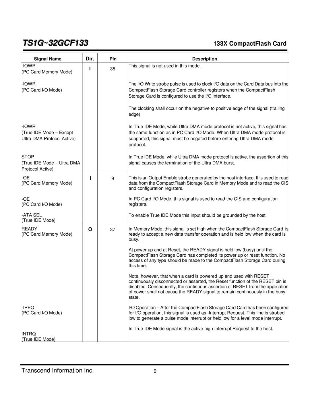
| Signal Name | Dir. | Pin | Description | |
| I | 35 | This signal is not used in this mode. | ||
(PC Card Memory Mode) |
|
| |||
|
|
|
| ||
|
| The I/O Write strobe pulse is used to clock I/O data on the Card Data bus into the | |||
(PC Card I/O Mode) |
|
| CompactFlash Storage Card controller registers when the CompactFlash | ||
|
|
|
| Storage Card is configured to use the I/O interface. | |
|
|
|
| The clocking shall occur on the negative to positive edge of the signal (trailing | |
|
|
|
| edge). | |
|
| In True IDE Mode, while Ultra DMA mode protocol is not active, this signal has | |||
(True IDE Mode – Except |
|
| the same function as in PC Card I/O Mode. When Ultra DMA mode protocol is | ||
Ultra DMA Protocol Active) |
|
| supported, this signal must be negated before entering Ultra DMA mode | ||
|
|
|
| protocol. | |
STOP |
|
| In True IDE Mode, while Ultra DMA mode protocol is active, the assertion of this | ||
(True IDE Mode – Ultra DMA |
|
| signal causes the termination of the Ultra DMA burst. | ||
Protocol Active) |
|
|
|
| |
I | 9 | This is an Output Enable strobe generated by the host interface. It is used to read | |||
(PC Card Memory Mode) |
|
| data from the CompactFlash Storage Card in Memory Mode and to read the CIS | ||
|
|
|
| and configuration registers. | |
|
| In PC Card I/O Mode, this signal is used to read the CIS and configuration | |||
(PC Card I/O Mode) |
|
| registers. | ||
|
| To enable True IDE Mode this input should be grounded by the host. | |||
(True IDE Mode) |
|
|
|
| |
READY | O | 37 | In Memory Mode, this signal is set high when the CompactFlash Storage Card is | ||
(PC Card Memory Mode) |
|
| ready to accept a new data transfer operation and is held low when the card is | ||
|
|
|
| busy. | |
|
|
|
| At power up and at Reset, the READY signal is held low (busy) until the | |
|
|
|
| CompactFlash Storage Card has completed its power up or reset function. No | |
|
|
|
| access of any type should be made to the CompactFlash Storage Card during | |
|
|
|
| this time. | |
|
|
|
| Note, however, that when a card is powered up and used with RESET | |
|
|
|
| continuously disconnected or asserted, the Reset function of the RESET pin is | |
|
|
|
| disabled. Consequently, the continuous assertion of RESET from the application | |
|
|
|
| of power shall not cause the READY signal to remain continuously in the busy | |
|
|
|
| state. | |
|
|
| I/O Operation – After the CompactFlash Storage Card Card has been configured | ||
(PC Card I/O Mode) |
|
| for I/O operation, this signal is used as | ||
|
|
|
| low to generate a pulse mode interrupt or held low for a level mode interrupt. | |
INTRQ |
|
| In True IDE Mode signal is the active high Interrupt Request to the host. | ||
|
|
|
| ||
(True IDE Mode) |
|
|
|
| |
Transcend Information Inc. | 9 |