S4TEF10xx-11x
Installation | Installation |
Switch set #1 - T1/E1 options | Switch set #2 - serial and ethernet options |
5, 6, 7, 8 -
The
•Switch 5 controls T1/E1 port 1
•Switch 6 controls T1/E1 port 2
•Switch 7 controls T1/E1 port 3
•Switch 8 controls T1/E1 port 4
When the
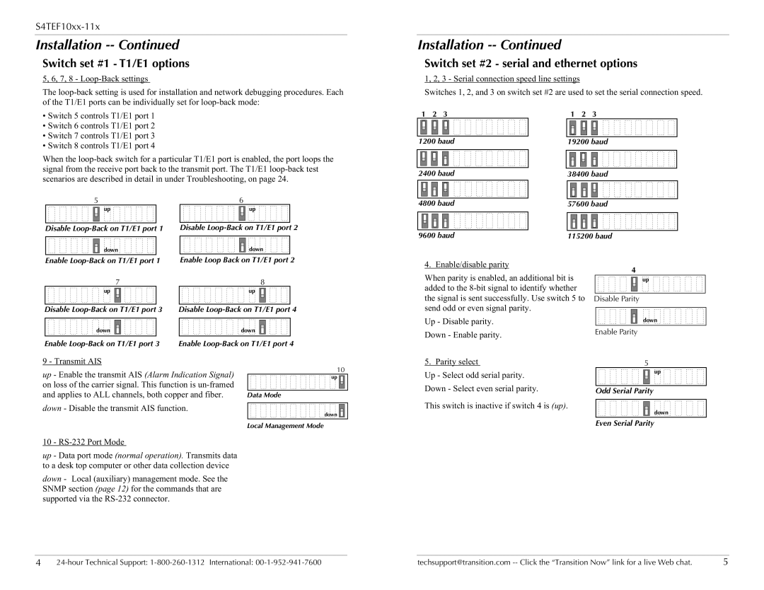
1, 2, 3 - Serial connection speed line settings
Switches 1, 2, and 3 on switch set #2 are used to set the serial connection speed.
1 | 2 | 3 | 1 | 2 | 3 |
1200 baud | 19200 baud | ||||
2400 baud | 38400 baud | ||||
5 | 6 | 4800 baud | 57600 baud | |
up | up | |||
|
| |||
Disable | Disable | 9600 baud | 115200 baud | |
|
| |||
down | down |
|
|
Enable | Enable Loop Back on T1/E1 port 2 |
7 | 8 |
up | up |
Disable | Disable |
down | down |
Enable | Enable |
4. Enable/disable parity
When parity is enabled, an additional bit is added to the
Up - Disable parity.
Down - Enable parity.
4
up |
Disable Parity
down |
Enable Parity
9 - Transmit AIS
up - Enable the transmit AIS (Alarm Indication Signal) on loss of the carrier signal. This function is
down - Disable the transmit AIS function.
10 - RS-232 Port Mode
up - Data port mode (normal operation). Transmits data to a desk top computer or other data collection device
down - Local (auxiliary) management mode. See the SNMP section (page 12) for the commands that are supported via the
10
up ![]()
Data Mode
down ![]()
![]()
![]()
![]()
Local Management Mode
5. Parity select | 5 |
Up - Select odd serial parity. | up |
| |
Down - Select even serial parity. | Odd Serial Parity |
This switch is inactive if switch 4 is (up).
down
Even Serial Parity
4 | techsupport@transition.com | 5 |