Transition Networks S4TEF10xx-11x Operation -- Continued, Fiber network LEDs, Ethernet LEDs

Models: S4TEF10xx-11x

1 15
Download 15 pages 21.32 Kb
Page 6
Image 6
Install the RS-232 data cable (included)

S4TEF10xx-11x

Installation -- Continued

Install the RS-232 data cable (included)

1.Use the enclosed RS-232 data cable with a male, DIN 6-pin connector on one end and a DB-9 connector installed on the other end.

2.Connect the DIN 6-pin connector to the RS-232 port on the S4TEF10xx-11x media converter.

3.Connect the DB-9 connector at the other end of the cable to the RS-232 port on a computer or other device that is used to collect and display data.

Operation

Fiber network LEDs

Use the status LEDs next to the fiber port to monitor the media converter and the fiber network connections.

LKF (fiber link)

ON = Fiber link connection.

PWR (power)

ON = Connection to external AC or DC power.

Operation -- Continued

Ethernet LEDs

Use the bi-color status LEDs (embedded in the 10/100Base-TX RJ-45 connector) to monitor the Ethernet connections.

Duplex/Link LED:

Amber = A link on the half-duplex twisted-pair copper link.

Flashing Amber = Activity on the half-duplex copper link.

Green = A link on the full-duplex twisted-pair copper link.

Flashing Green = Activity on the full-duplex copper link.

Speed LED:

Amber = 10 Mb/s operation.

Green = 100 Mb/s operation.

AutoCross™

The AutoCross feature allows either straight-through (MDI) or crossover (MDI-X) cables to be used when connecting to devices such as hubs, transceivers, or network interface cards (NICs). AutoCross determines the characteristics of the cable connection and automatically configures the unit to link up, regardless of the cable configuration.

T1/E1 LEDs

Each T1/E1 link has a pair of LEDs embedded in the RJ-48 connector that monitor the status of the link.

LNK LED

ON = T1/E1 link detected.

Dry-contact relay

All four T1/E1 ports are equipped with an RJ-48 dry-contact relay. The relay closes if the power is lost or if any of the individual T1/E1 links are lost. The operational rating on pins 3 and 6 are 0-30 VDC, 100 mA (maximum).

T1/E1 port

3

relay

6

RJ-48C connector

OFF= T1/E1 signal lost or no signal.

AIS LED

ON = AIS (Alarm Indication Signal) detected. Failure of the device connected to the T1/E1 port.
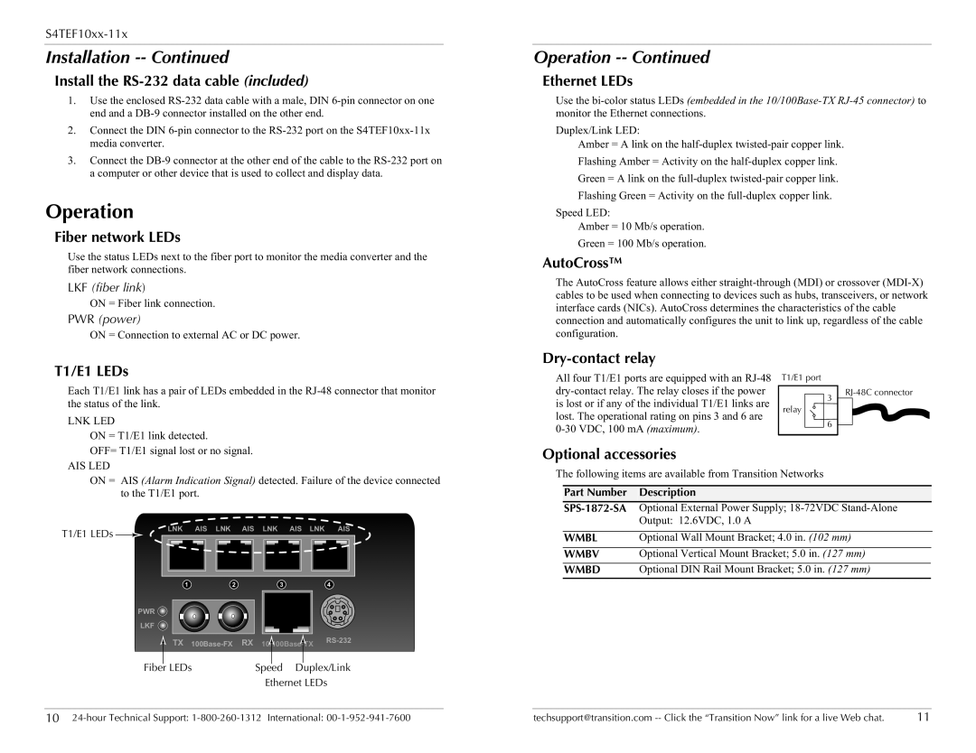
T1/E1 LEDs

LNK

AIS

LNK

AIS

LNK

AIS

LNK

AIS


1


2


3


4


PWR


LKF


TX 100Base-FX RX


10/100Base-TX

RS-232


Fiber


LEDs

Speed Duplex/Link


Ethernet LEDs

Optional accessories

The following items are available from Transition Networks

Part Number

Description

SPS-1872-SAOptional External Power Supply; 18-72VDC Stand-Alone


Output: 12.6VDC, 1.0 A


WMBL

Optional Wall Mount Bracket; 4.0 in. (102 mm)

WMBV

Optional Vertical Mount Bracket; 5.0 in. (127 mm)

WMBD

Optional DIN Rail Mount Bracket; 5.0 in. (127 mm)

10 24-hour Technical Support: 1-800-260-1312 International: 00-1-952-941-7600

techsupport@transition.com -- Click the “Transition Now” link for a live Web chat.

11

Page 6
Image 6
Transition Networks S4TEF10xx-11x Operation -- Continued, Install the RS-232 data cable included, Fiber network LEDs