S4TEF10xx-11x
Installation — Continued
Hardware/software jumper
The jumper is located on the circuit board, inside the media
converter housing. | S |
|
|
|
| H |
|
|
|
|
|
| |
Hardware: |
| Software Mode | ||||
The media converter mode is determined by the | switch |
|
|
|
|
|
setting (see pages 3 - 7). | S |
|
|
|
| H |
|
|
|
|
|
|
|
Software: | Hardware Mode | |||||
The media converter mode is determined by the
To set the jumper:
Installation -- Continued
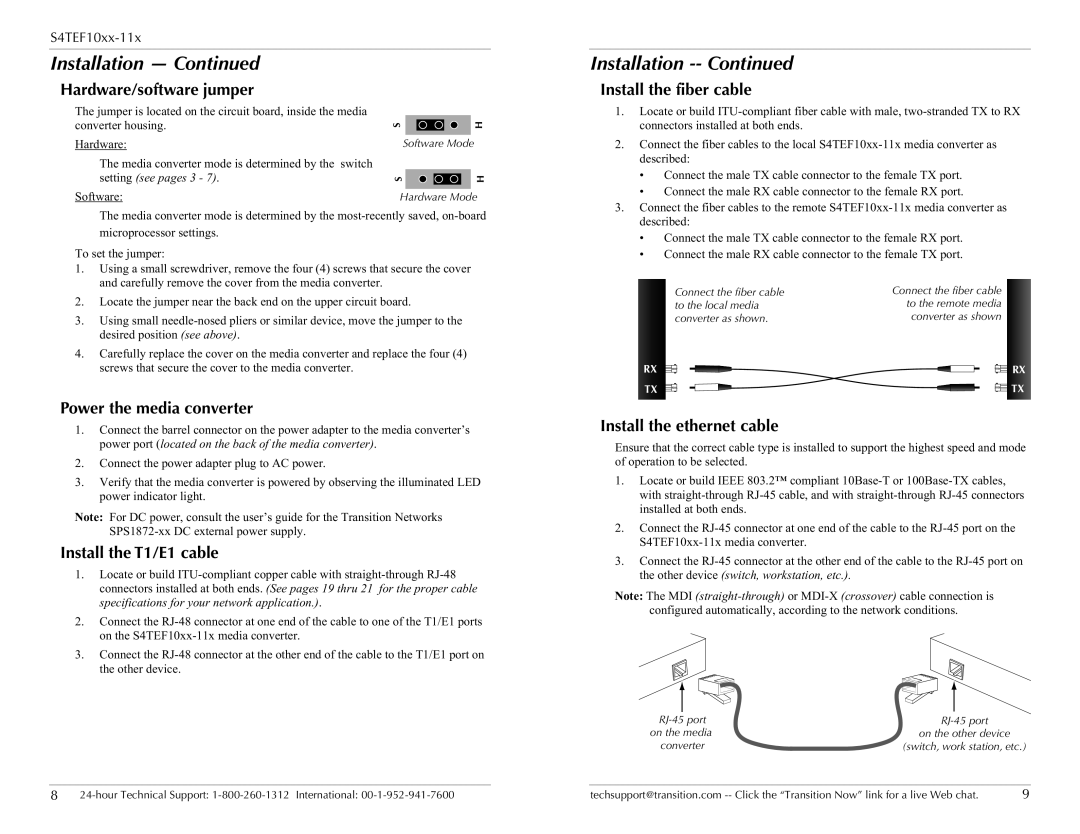
Install the fiber cable
1.Locate or build
2.Connect the fiber cables to the local
•Connect the male TX cable connector to the female TX port.
•Connect the male RX cable connector to the female RX port.
3.Connect the fiber cables to the remote
•Connect the male TX cable connector to the female RX port.
•Connect the male RX cable connector to the female TX port.
1.Using a small screwdriver, remove the four (4) screws that secure the cover and carefully remove the cover from the media converter.
2.Locate the jumper near the back end on the upper circuit board.
3.Using small
4.Carefully replace the cover on the media converter and replace the four (4) screws that secure the cover to the media converter.
Power the media converter
Connect the fiber cable to the local media converter as shown.
RX
TX
Connect the fiber cable to the remote media converter as shown
RX
![]() TX
TX
1.Connect the barrel connector on the power adapter to the media converter’s power port (located on the back of the media converter).
2.Connect the power adapter plug to AC power.
3.Verify that the media converter is powered by observing the illuminated LED power indicator light.
Note: For DC power, consult the user’s guide for the Transition Networks
Install the T1/E1 cable
1.Locate or build
2.Connect the
3.Connect the
Install the ethernet cable
Ensure that the correct cable type is installed to support the highest speed and mode of operation to be selected.
1.Locate or build IEEE 803.2™ compliant
2.Connect the
3.Connect the
Note: The MDI
configured automatically, according to the network conditions.
|
|
|
|
|
|
|
|
|
|
|
|
|
|
|
|
|
|
|
|
|
|
|
|
|
| ||||
on the media | on the other device | ||||
converter | (switch, work station, etc.) | ||||
|
|
|
|
|
|
8 | techsupport@transition.com | 9 |