Enables Loop-Back
Disables Loop-Back
S4TEF10xx-11x
Installation — Continued
Switch set #2 - serial and ethernet options
Installation -- Continued |
Switch set #2 - serial and ethernet options |
6 - Twisted-pair Auto-Negotiation
Up (Enabled) - The media converter “advertises” ALL rate and mode capabilities to the network:
•100 Mb/s full- or half-duplex
•10 Mb/s full- or half-duplex
The media converter brings up the Ethernet link to the highest speed and mode possible for all the attached network devices.
6
Enable Auto-Negotiation
down
Disable Auto-Negotiation
9 - Transparent Link Pass-Through | 9 |
| up |
Up - Enable Link Pass-Through | |
Down - Disable Link Pass-Through | Enable Link Pass-Through |
| down |
| Disable Link Pass-Through |
When selected, Auto-Negotiation allows a twisted-pair link to become operational only after the Auto-Negotiation function matches network speed capabilities at both ends of the twisted-pair copper segment.
down (Disabled) - The bridging media converter does not “advertise” the rate and mode capabilities to the network. Switch 7 and switch 8 are then used to set the speed and mode for the Ethernet link.
Note: Switch 7 and 8 are inactive if switch 6 is enabled (up).
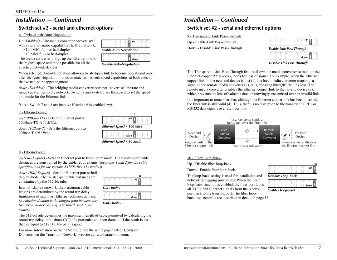
The Transparent Link Pass-Through feature allows the media converter to monitor the Ethernet copper RX (receive) ports for loss of signal. For example, when the Ethernet copper link on the near end device is lost (1), the local media converter transmits a signal to the remote media converter (2), thus, “passing through” the link loss. The remote media converter disables the Ethernet copper link to the far-end device (3), which prevents the loss of valuable data unknowingly transmitted over an invalid link.
It is important to remember that, although the Ethernet copper link has been disabled, the fiber link is still valid (4). Thus, there is no disruption to the transfer of T1/E1 or RS-232 data signals over the fiber link.
7 - Ethernet speed
up (100Base-TX)- Sets the Ethernet port to 100Base-TX (100 Mb/s).
down (10Base-T)- Sets the Ethernet port to 10Base-T (10 Mb/s).
7
Ethernet Speed = 100 Mb/s
local converter sends a loss signal over the fiber link
Ethernet Speed = 10 Mb/s
original fault on the Ethernet copper link
4 |
fiber link is still valid |
remote converter disables the Ethernet copper link
8 - Ethernet node
up (Full-Duplex)- Sets the Ethernet port to full-duplex mode. The twisted-pair cable distances are constrained by the cable requirements (see pages 1 and 2 for the cable specifications for the various S4TEF10xx-11x models).
10 - Fiber Loop-Back | |
Up - Disable fiber loop-back. | 10 |
Down - Enable fiber loop-back. | up |
|
down (Half-Duplex)- Sets the Ethernet port to half- duplex mode. The twisted-pair cable distances are constrained by the 512-bit rule:
In a half-duplex network, the maximum cable lengths are determined by the round trip delay limitations of each Fast Ethernet collision domain. (A collision domain is the longest path between any two terminal devices, e.g. a terminal, switch, or router.)
8
Full-Duplex
down 


Half-Duplex
The loop-back setting is used for installation and network debugging procedures. When the fiber
loop-back function is enabled, the fiber port loopsdown 
 all T1/E1 and Ethernet signals from the receive
port back to the transmit port. The fiber loop-
back test scenarios are described in detail on page 18.
The 512-bit rule determines the maximum length of cable permitted by calculating the round-trip delay in bit-times (BT) of a particular collision domain. If the result is less than or equal to 512 BT, the path is good.
For more information on the 512-bit rule, see the white paper titled “Collision Domains” on the Transition Networks website at: www.transition.com.
6 | 24-hour Technical Support: 1-800-260-1312 International: 00-1-952-941-7600 | techsupport@transition.com -- Click the “Transition Now” link for a live Web chat. | 7 |