IV. OPERATION/START-UP

IV. a - MASTER SWITCH:

The master switch is located at main electrical box behind the louver panel and should be in the OFF po- sition.

IV. b - POWER SUPPLY:

Connect the power supply cord to the proper fused receptacle in accordance with state and local codes.

IV. c - CONDENSING UNIT:

The condensing unit is cycled by a low pressure con- trol set at approximately 52 lbs. cut-in, 18 lbs. cut-out.

All valves on the condensing unit are open when shipped. Check all connections for leaks with an elec- tronic detector before starting unit.

IV. d - TURNING THE UNIT ON:

Turn the master switch to the ON position.

IV. e - CHECKING THE TEMPERATURE:

Check the temperature of the refrigerated unit to in- sure cooling is being obtained, and adjust the temp control as needed. Re-check operation after several hours and again after two or three days.

IV. f - OPTIONAL LCD THERMOMETER:

If supplied with an optional LCD thermometer, to acti- vate remove paper film from LCD thermometer bat- tery contacts by opening the louver panel and reach- ing behind the thermometer to access batteries (AA batteries included).

IV. g - DEFROST TIMER:

Set defrost timer to correct time of day after unit is plugged in. Pins are set from the factory, EXAMPLE: 10am, 2pm, 8pm, 2am and 6am. A minimum of five (5) defrost cycles are required per day.

IV. h - ADJUSTING THE TEMPERATURE:

The refrigeration system has been properly charged and tested at the factory. It is regulated by an elec- tronic control.

All control settings are retained in a non-volatile memory. If the power supply is interrupted for any reason, re-programming is not necessary unless dif- ferent control settings are required.

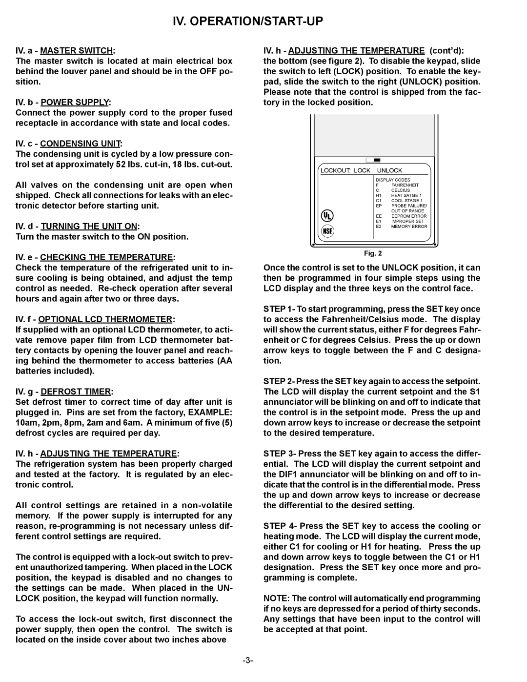
The control is equipped with a lock-out switch to prev- ent unauthorized tampering. When placed in the LOCK position, the keypad is disabled and no changes to the settings can be made. When placed in the UN- LOCK position, the keypad will function normally.

To access the lock-out switch, first disconnect the power supply, then open the control. The switch is located on the inside cover about two inches above

-3-

IV. h - ADJUSTING THE TEMPERATURE (cont’d): the bottom (see figure 2). To disable the keypad, slide the switch to left (LOCK) position. To enable the key- pad, slide the switch to the right (UNLOCK) position. Please note that the control is shipped from the fac- tory in the locked position.

LOCKOUT: LOCK UNLOCK


DISPLAY CODES


F

FAHRENHEIT


C

CELCIUS


H1

HEAT SATGE 1


C1

COOL STAGE 1


EP

PROBE FAILURE/


OUT OF RANGE

R

EE

EEPROM ERROR

E1

IMPROPER SET


E2

MEMORY ERROR


Fig. 2

Once the control is set to the UNLOCK position, it can then be programmed in four simple steps using the LCD display and the three keys on the control face.

STEP 1- To start programming, press the SET key once to access the Fahrenheit/Celsius mode. The display will show the current status, either F for degrees Fahr- enheit or C for degrees Celsius. Press the up or down arrow keys to toggle between the F and C designa- tion.

STEP 2- Press the SET key again to access the setpoint. The LCD will display the current setpoint and the S1 annunciator will be blinking on and off to indicate that the control is in the setpoint mode. Press the up and down arrow keys to increase or decrease the setpoint to the desired temperature.

STEP 3- Press the SET key again to access the differ- ential. The LCD will display the current setpoint and the DIF1 annunciator will be blinking on and off to in- dicate that the control is in the differential mode. Press the up and down arrow keys to increase or decrease the differential to the desired setting.

STEP 4- Press the SET key to access the cooling or heating mode. The LCD will display the current mode, either C1 for cooling or H1 for heating. Press the up and down arrow keys to toggle between the C1 or H1 designation. Press the SET key once more and pro- gramming is complete.

NOTE: The control will automatically end programming if no keys are depressed for a period of thirty seconds. Any settings that have been input to the control will be accepted at that point.

Page 4
Image 4
Traulsen VPS48S, VPS72S, VPS90S, VPS66S, VPS54S, VPS114S owner manual Iv. Operation/Start-Up, Lockout Lock Unlock

VPS114S, VPS48S, VPS54S, VPS66S, VPS90S specifications

The Traulsen line of pass-thru refrigerators, specifically the VPS72S, VPS90S, VPS66S, VPS54S, and VPS48S, offers excellent storage solutions for commercial kitchens in need of reliable and high-capacity refrigeration. These units are engineered for efficiency, durability, and ease of use, making them ideal for restaurants, catering services, and other food service operations.

The VPS series features stainless steel construction both inside and out, providing durability that withstands the rigors of a busy kitchen environment. The seamless, one-piece design not only adds to the unit's cleanliness and sanitation but also enhances its aesthetic appeal. The heavy-duty recessed door handles are designed for smooth operation, allowing for quick access to items stored within.

One of the standout technologies in the Traulsen VPS series is the energy-efficient refrigeration system. Each model is designed to maintain consistent temperatures, keeping food products safe and fresh. The advanced digital temperature control ensures precision, while the forced air refrigeration system facilitates even temperature distribution and eliminates hot spots.

Another remarkable characteristic of these models is their interior configuration. Adjustable shelves allow for customizable storage solutions, accommodating various types of food products, from bulk items to smaller ingredients. Furthermore, the stainless steel shelving is not only durable but easily removable for thorough cleaning.

The VPS series refrigerators are also equipped with advanced compressor technology that enhances energy efficiency and reduces operational costs. The insulated double doors feature a self-closing mechanism, minimizing temperature fluctuations when the doors are opened frequently. The pass-thru design allows for convenient access from both sides, optimizing workflow in busy kitchens.

Additionally, each model in the Traulsen VPS line complies with the highest industry standards for safety and performance. They are equipped with a reliable high-temperature alarm, ensuring that kitchen staff is alerted to any fluctuations in temperature that could jeopardize food safety.

Overall, the Traulsen VPS72S, VPS90S, VPS66S, VPS54S, and VPS48S are designed for commercial establishments looking for high-capacity, energy-efficient refrigeration options. With robust construction, advanced technologies, and customizable configurations, these units provide an optimal blend of performance and functionality for any kitchen setting.