Configuration
Set Configuration DIP Switches
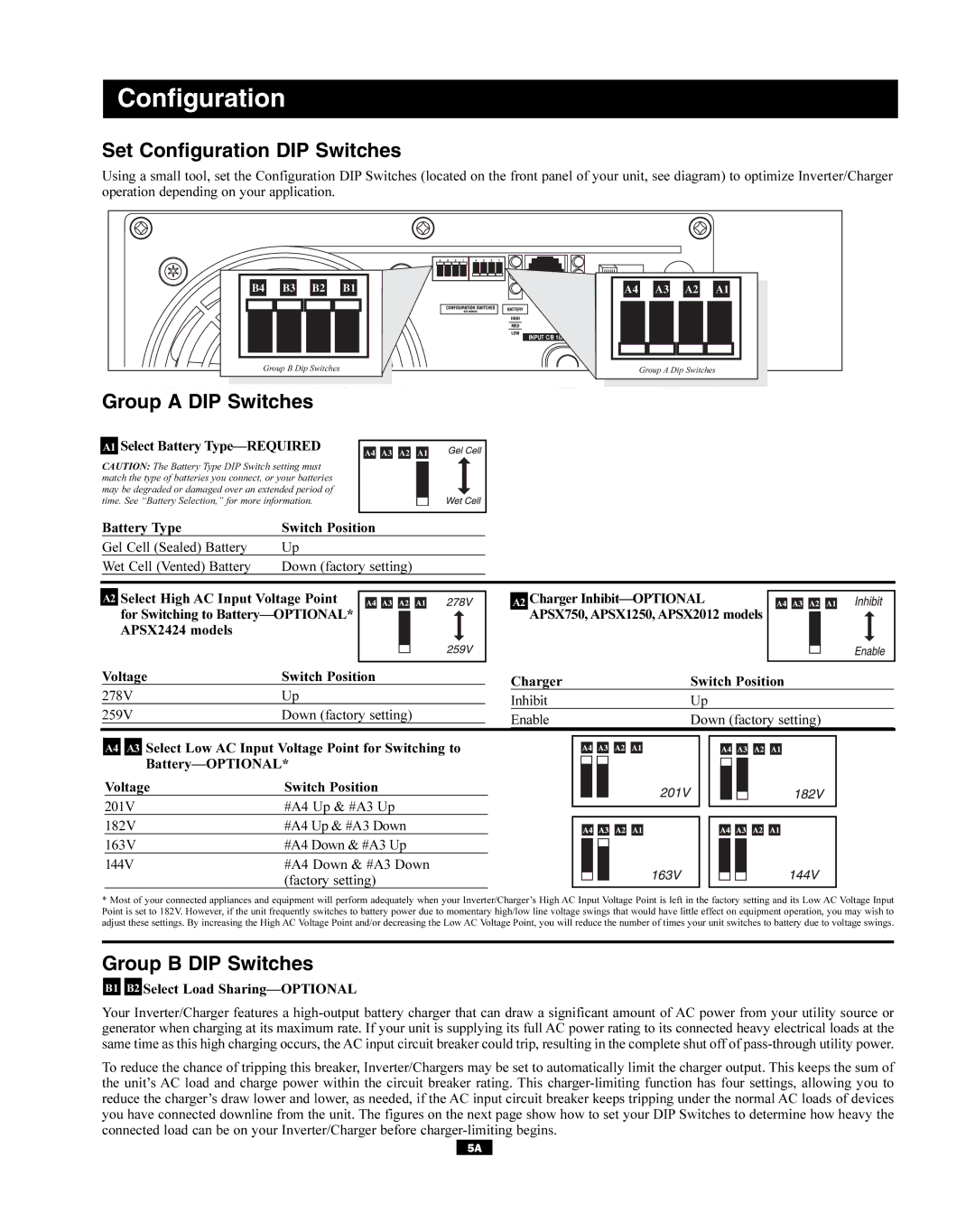
Using a small tool, set the Configuration DIP Switches (located on the front panel of your unit, see diagram) to optimize Inverter/Charger operation depending on your application.
B4 | B3 | B2 | B1 |
|
|
| INPUT C/B |
Group B Dip Switches |
| ||
A4 | A3 | A2 | A1 |
| OUTPUT C/B 12A |
| |
Group A Dip Switches
Group A DIP Switches
A1 Select Battery
CAUTION: The Battery Type DIP Switch setting must match the type of batteries you connect, or your batteries may be degraded or damaged over an extended period of time. See “Battery Selection,” for more information.
A4 A3 A2 A1
Battery Type | Switch Position |
Gel Cell (Sealed) Battery | Up |
Wet Cell (Vented) Battery | Down (factory setting) |
| A2 | Select High AC Input Voltage Point |
|
|
|
|
|
|
|
|
| |||
|
|
|
|
| ||||||||||
|
| for Switching to |
|
|
|
|
|
|
|
|
|
|
| |
|
|
|
|
|
|
| ||||||||
|
| APSX2424 models |
|
|
|
|
|
|
|
|
|
|
|
|
|
|
|
|
|
|
|
|
|
|
|
|
|
|
|
|
|
|
| |||||||||||
| Voltage | Switch Position | ||||||||||||
| 278V | Up | ||||||||||||
| 259V | Down (factory setting) | ||||||||||||
. |
|
|
|
|
|
|
|
|
|
|
|
|
| |
A2 Charger
Charger | Switch Position |
Inhibit | Up |
Enable | Down (factory setting) |
A4 A3 Select Low AC Input Voltage Point for Switching to
Voltage | Switch Position |
201V | #A4 Up & #A3 Up |
182V | #A4 Up & #A3 Down |
163V | #A4 Down & #A3 Up |
144V | #A4 Down & #A3 Down |
| (factory setting) |
*Most of your connected appliances and equipment will perform adequately when your Inverter/Charger’s High AC Input Voltage Point is left in the factory setting and its Low AC Voltage Input Point is set to 182V. However, if the unit frequently switches to battery power due to momentary high/low line voltage swings that would have little effect on equipment operation, you may wish to adjust these settings. By increasing the High AC Voltage Point and/or decreasing the Low AC Voltage Point, you will reduce the number of times your unit switches to battery due to voltage swings.
Group B DIP Switches
B1 B2 Select Load Sharing—OPTIONAL
Your Inverter/Charger features a
To reduce the chance of tripping this breaker, Inverter/Chargers may be set to automatically limit the charger output. This keeps the sum of the unit’s AC load and charge power within the circuit breaker rating. This
5A