Introduction (continued)
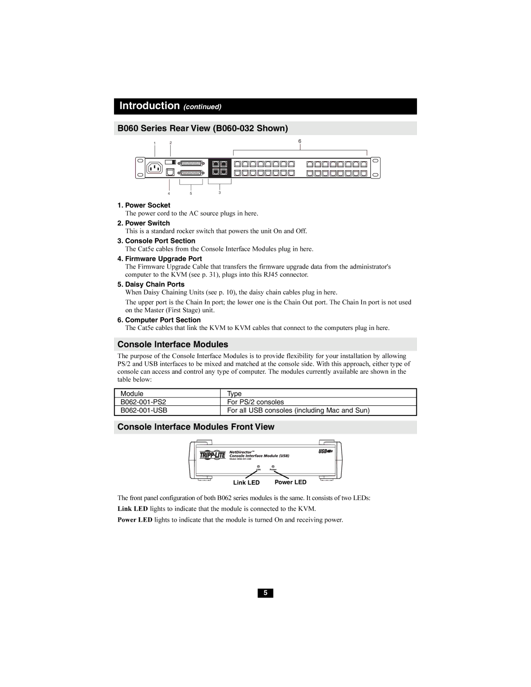
B060 Series Rear View (B060-032 Shown)
1 | 2 | 6 |
4 | 5 | 3 |
1.Power Socket
The power cord to the AC source plugs in here.
2.Power Switch
This is a standard rocker switch that powers the unit On and Off.
3.Console Port Section
The Cat5e cables from the Console Interface Modules plug in here.
4.Firmware Upgrade Port
The Firmware Upgrade Cable that transfers the firmware upgrade data from the administrator's computer to the KVM (see p. 31), plugs into this RJ45 connector.
5.Daisy Chain Ports
When Daisy Chaining Units (see p. 10), the daisy chain cables plug in here.
The upper port is the Chain In port; the lower one is the Chain Out port. The Chain In port is not used on the Master (First Stage) unit.
6.Computer Port Section
The Cat5e cables that link the KVM to KVM cables that connect to the computers plug in here.
Console Interface Modules
The purpose of the Console Interface Modules is to provide flexibility for your installation by allowing PS/2 and USB interfaces to be mixed and matched at the console side. With this approach, either type of console can access and control any type of computer. The modules currently available are shown in the table below:
Module | Type |
For PS/2 consoles | |
For all USB consoles (including Mac and Sun) |
Console Interface Modules Front View
Link LED | Power LED |
The front panel configuration of both B062 series modules is the same. It consists of two LEDs: Link LED lights to indicate that the module is connected to the KVM.
Power LED lights to indicate that the module is turned On and receiving power.
5