B070-016-19-IP specifications
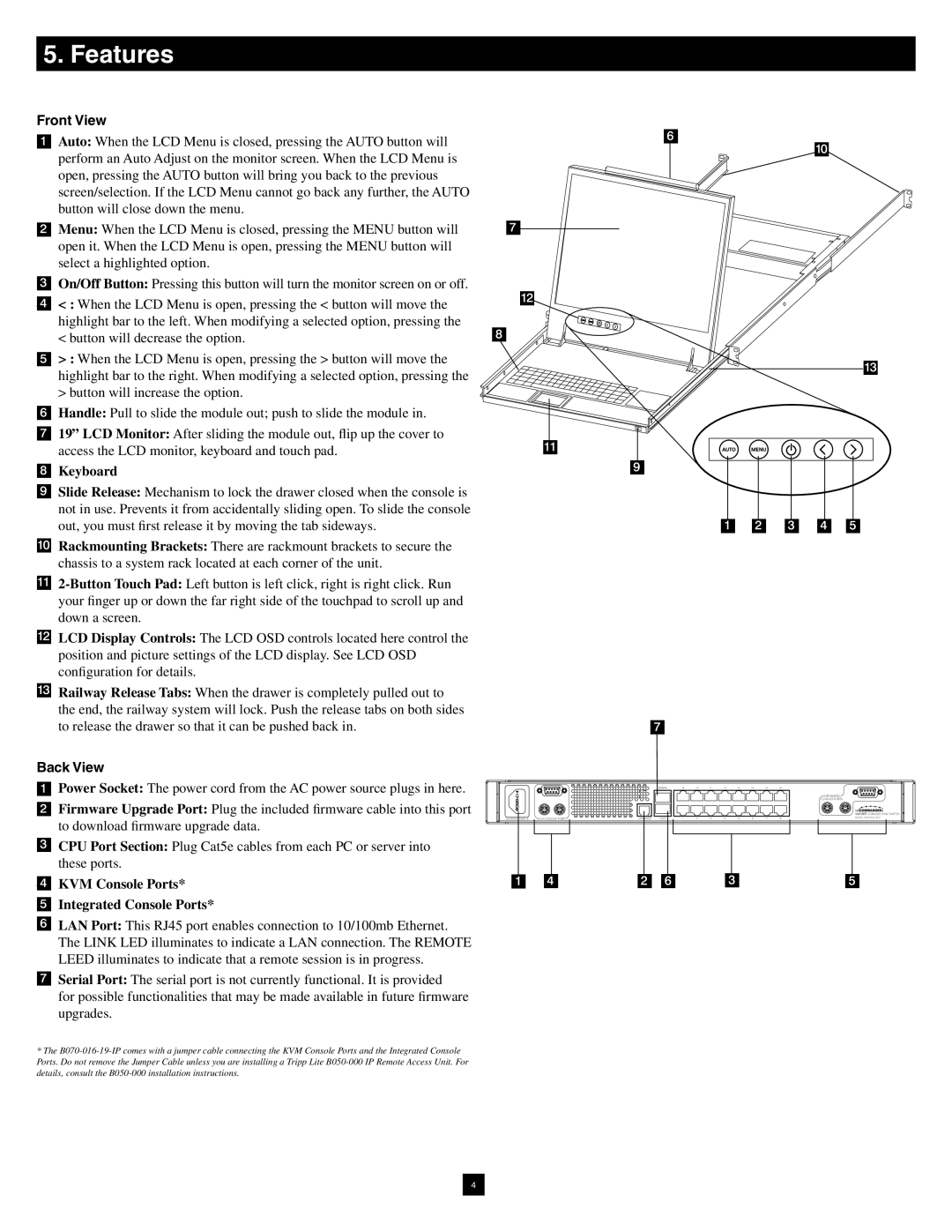
The Tripp Lite B070-016-19-IP is a highly versatile 16-port KVM switch that serves as a reliable solution for managing multiple servers or computers from a single set of keyboard, video monitor, and mouse. This device is particularly useful in data centers, server rooms, and other environments where space and efficient management are crucial.One of the standout features of the B070-016-19-IP is its ability to support remote access. With built-in IP capabilities, administrators can manage connected devices from anywhere in the world, enhancing operational efficiency. This is particularly important in today's increasingly mobile work environments, where remote troubleshooting and management can save time and resources.
The switch supports a variety of video resolutions up to 1920 x 1200, which ensures sharp and clear visual output, making it suitable for high-definition applications. Additionally, it is compatible with all major operating systems, further ensuring versatility in a multi-platform environment. The B070-016-19-IP features a compact design that can be easily integrated into existing systems without requiring significant reconfiguration.
The device employs advanced security measures for remote access, including enhanced encryption to protect sensitive data and server access. This includes features such as user authentication and various access levels, ensuring that only authorized personnel can manage the systems.
Built for durability and reliability, the Tripp Lite B070-016-19-IP is designed with robust construction that can withstand the rigors of daily operation in demanding environments. The device also includes a built-in firmware upgrade capability, keeping it up to date with the latest advancements and features.
In terms of connectivity, the switch offers multiple interfaces, allowing for seamless integration with various hardware configurations. It utilizes standard RJ-45 ports for connection, making installation straightforward and efficient.
Overall, the Tripp Lite B070-016-19-IP KVM switch stands out for its powerful blend of features, flexibility, and security, making it an ideal choice for IT professionals who require efficient management of multiple servers or computers. Whether used in a data center or an office, this KVM switch provides the tools necessary for effective system administration and optimal resource utilization.

