Connection continued
1Hardwire your isolation transformer’s UPS connector to your UPS’s input and output.
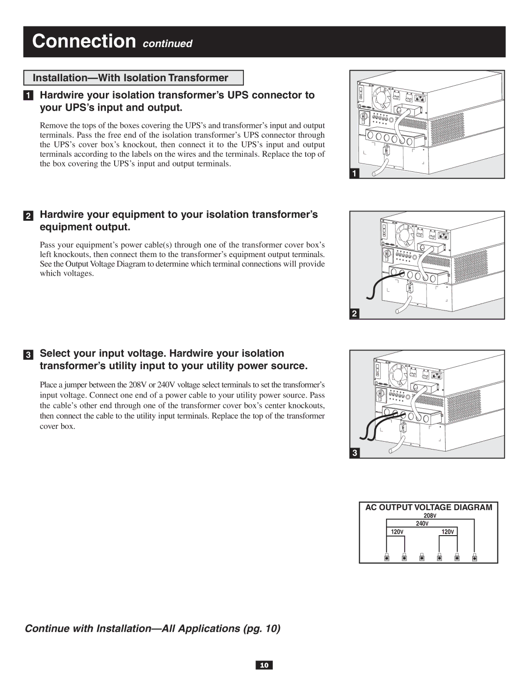
Remove the tops of the boxes covering the UPS’s and transformer’s input and output terminals. Pass the free end of the isolation transformer’s UPS connector through the UPS’s cover box’s knockout, then connect it to the UPS’s input and output terminals according to the labels on the wires and the terminals. Replace the top of the box covering the UPS’s input and output terminals.
1 |
2Hardwire your equipment to your isolation transformer’s
equipment output.
Pass your equipment’s power cable(s) through one of the transformer cover box’s left knockouts, then connect them to the transformer’s equipment output terminals. See the Output Voltage Diagram to determine which terminal connections will provide which voltages.
2
3Select your input voltage. Hardwire your isolation
transformer’s utility input to your utility power source.
Place a jumper between the 208V or 240V voltage select terminals to set the transformer’s input voltage. Connect one end of a power cable to your utility power source. Pass the cable’s other end through one of the transformer cover box’s center knockouts, then connect the cable to the utility input terminals. Replace the top of the transformer cover box.
3
AC OUTPUT VOLTAGE DIAGRAM
208V
240V
120V120V
Continue with
10