Connection continued
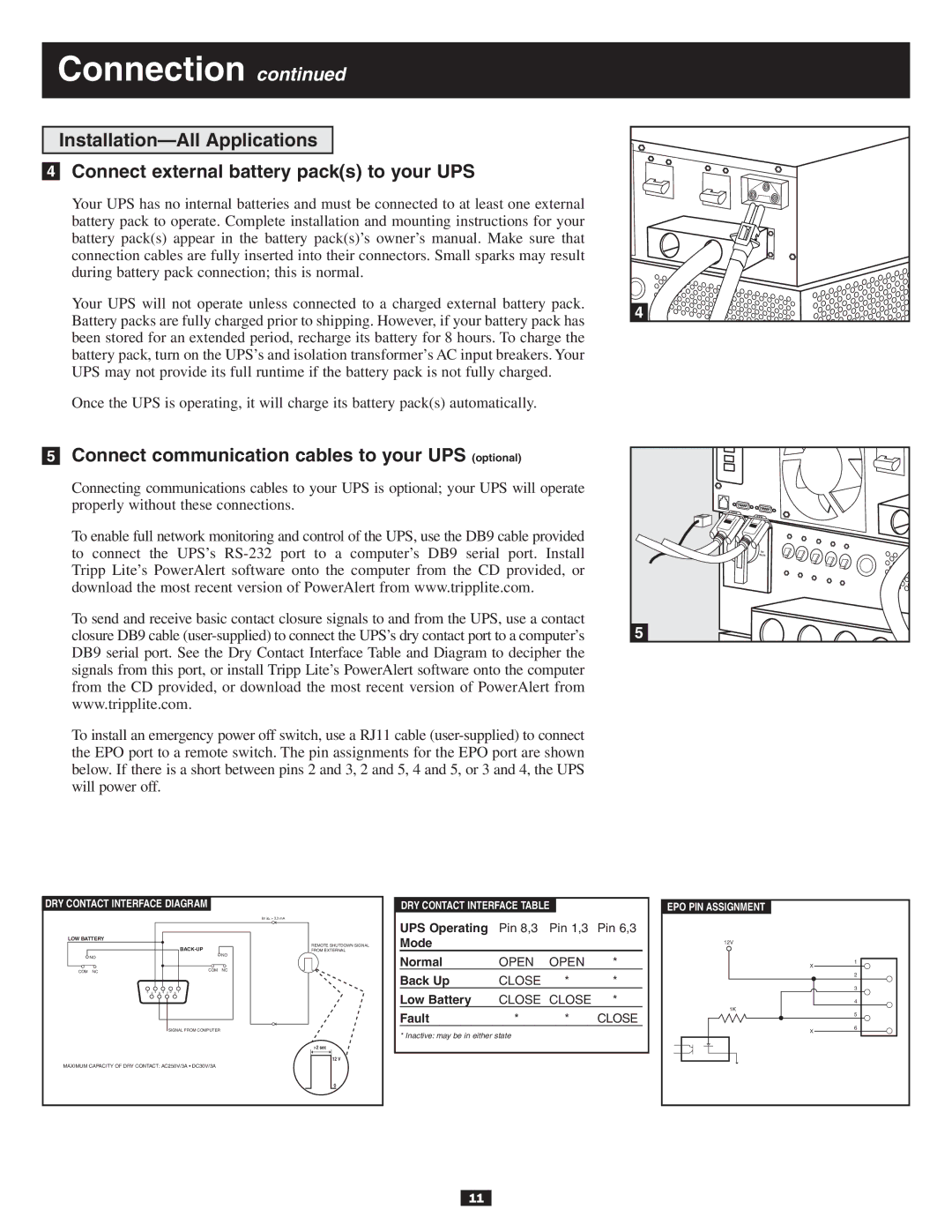
4Connect external battery pack(s) to your UPS
Your UPS has no internal batteries and must be connected to at least one external battery pack to operate. Complete installation and mounting instructions for your battery pack(s) appear in the battery pack(s)’s owner’s manual. Make sure that connection cables are fully inserted into their connectors. Small sparks may result during battery pack connection; this is normal.
Your UPS will not operate unless connected to a charged external battery pack. Battery packs are fully charged prior to shipping. However, if your battery pack has been stored for an extended period, recharge its battery for 8 hours. To charge the battery pack, turn on the UPS’s and isolation transformer’s AC input breakers. Your UPS may not provide its full runtime if the battery pack is not fully charged.
Once the UPS is operating, it will charge its battery pack(s) automatically.
5Connect communication cables to your UPS (optional)
Connecting communications cables to your UPS is optional; your UPS will operate properly without these connections.
To enable full network monitoring and control of the UPS, use the DB9 cable provided to connect the UPS’s
To send and receive basic contact closure signals to and from the UPS, use a contact closure DB9 cable
To install an emergency power off switch, use a RJ11 cable
4
NORMAL |
BY |
PASS |
5 |
DRY CONTACT INTERFACE DIAGRAM
|
|
|
|
|
|
| lm in. > 3.3 mA |
LOW BATTERY |
|
|
|
|
|
|
|
|
|
|
|
|
|
| REMOTE SHUTDOWN SIGNAL |
|
|
|
|
|
| FROM EXTERNAL | |
NO |
|
|
|
|
|
| NO |
|
|
|
|
|
|
| |
COM NC |
|
|
|
|
| COM | NC |
|
|
|
|
|
|
| |
5 | 9 4 | 8 | 3 | 7 2 | 6 | 1 |
|
|
|
|
| SIGNAL FROM COMPUTER |
| ||
|
|
|
|
|
|
| >2 sec |
|
|
|
|
|
|
| 12 V |
MAXIMUM CAPACITY OF DRY CONTACT: AC250V/3A • DC30V/3A |
| ||||||
|
|
|
|
|
|
| 0 |
| DRY CONTACT INTERFACE TABLE |
|
| ||
| UPS Operating | Pin 8,3 | Pin 1,3 | Pin 6,3 | |
| Mode |
|
|
|
|
| Normal | OPEN | OPEN | * | |
| Back Up | CLOSE | * | * | |
| Low Battery | CLOSE | CLOSE | * | |
| Fault | * | * | CLOSE | |
* Inactive: may be in either state
EPO PIN ASSIGNMENT
12V |
|
X | 1 |
| |
| 2 |
| 3 |
| 4 |
1K | 5 |
| |
X | 6 |
|
11