Power Module Features (continued)
Communication Interface
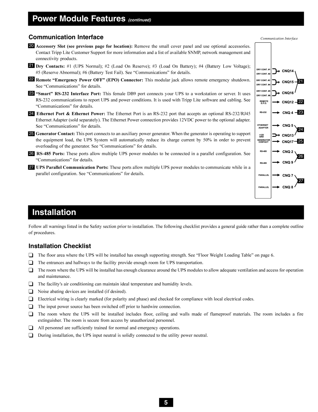
Communication Interface
20Accessory Slot (see previous page for location): Remove the small cover panel and use optional accessories. Contact Tripp Lite Customer Support for more information and a list of available SNMP, network management and connectivity products.
21Dry Contacts: #1 (UPS Normal); #2 (Load On Reserve); #3 (Load On Battery); #4 (Battery Low Voltage); #5 (Reserve Abnormal); #6 (Battery Test Fail). See “Communications” for details.
22Remote “Emergency Power OFF” (EPO) Connector: This modular jack allows remote emergency shutdown. See “Communications” for details.
23“Smart”
24Ethernet Port & Ethernet Power: The Ethernet Port is an
25Generator Contact: This port connects to an auxiliary power generator. When the generator is operating to support the equipment load, the UPS System will automatically reduce its charge current by 50% in order to prevent overloading of the generator. See “Communications” for details.
26
27UPS Parallel Communication Ports: These ports allow multiple UPS power modules to communicate while in a parallel configuration. See “Communications” for details.
![]()
![]()
![]()
![]()
![]()
![]()
![]()
![]()
![]()
![]()
![]()
![]()
![]()
![]() 21
21
![]()
![]()
![]()
![]()
![]() 22
22
![]()
![]()
![]()
![]() 23
23
![]() 24
24
![]()
![]()
![]()
![]() 25
25
![]() 26
26
![]() 27
27
Installation
Follow all warnings listed in the Safety section prior to installation. The following checklist provides a general guide rather than a complete outline of procedures.
Installation Checklist
❑The floor area where the UPS will be installed has enough supporting strength. See “Floor Weight Loading Table” on page 6.
❑The entrances and hallways to the facility provide enough room for UPS transportation.
❑The room where the UPS will be installed has enough clearance around the UPS modules to allow adequate ventilation and access for operation and maintenance.
❑The facility's air conditioning can maintain ideal temperature and humidity levels.
❑Noise abating devices are installed (if desired).
❑Electrical wiring is clearly marked (for polarity and phase) and checked for compliance with local electrical codes.
❑The input power source has been switched off prior to hardwire connection.
❑The room where the UPS will be installed includes floor, ceiling and walls made of flameproof materials. The room includes a fire extinguisher. The room is secure from access by unauthorized personnel.
❑All personnel are sufficiently trained for normal and emergency operations.
❑During installation, the UPS input neutral is solidly connected to the utility power neutral.
5