Installation (continued)
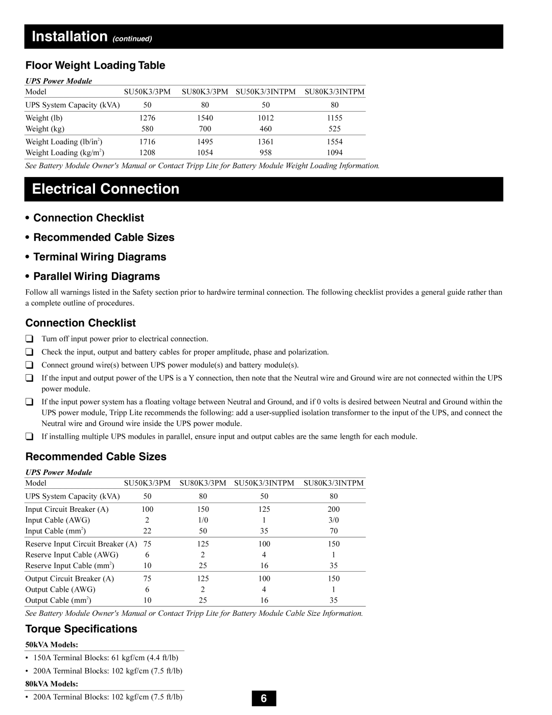
Floor Weight Loading Table
UPS Power Module
Model | SU50K3/3PM | SU80K3/3PM | SU50K3/3INTPM | SU80K3/3INTPM |
|
|
|
|
|
UPS System Capacity (kVA) | 50 | 80 | 50 | 80 |
|
|
|
|
|
Weight (lb) | 1276 | 1540 | 1012 | 1155 |
Weight (kg) | 580 | 700 | 460 | 525 |
|
|
|
|
|
Weight Loading (lb/in2) | 1716 | 1495 | 1361 | 1554 |
Weight Loading (kg/m2) | 1208 | 1054 | 958 | 1094 |
See Battery Module Owner's Manual or Contact Tripp Lite for Battery Module Weight Loading Information.
Electrical Connection
•Connection Checklist
•Recommended Cable Sizes
•Terminal Wiring Diagrams
•Parallel Wiring Diagrams
Follow all warnings listed in the Safety section prior to hardwire terminal connection. The following checklist provides a general guide rather than a complete outline of procedures.
Connection Checklist
❑Turn off input power prior to electrical connection.
❑Check the input, output and battery cables for proper amplitude, phase and polarization.
❑Connect ground wire(s) between UPS power module(s) and battery module(s).
❑If the input and output power of the UPS is a Y connection, then note that the Neutral wire and Ground wire are not connected within the UPS power module.
❑If the input power system has a floating voltage between Neutral and Ground, and if 0 volts is desired between Neutral and Ground within the UPS power module, Tripp Lite recommends the following: add a
❑If installing multiple UPS modules in parallel, ensure input and output cables are the same length for each module.
Recommended Cable Sizes
UPS Power Module
Model | SU50K3/3PM | SU80K3/3PM | SU50K3/3INTPM | SU80K3/3INTPM |
UPS System Capacity (kVA) | 50 | 80 | 50 | 80 |
|
|
|
|
|
Input Circuit Breaker (A) | 100 | 150 | 125 | 200 |
Input Cable (AWG) | 2 | 1/0 | 1 | 3/0 |
Input Cable (mm2) | 22 | 50 | 35 | 70 |
|
|
|
| |
Reserve Input Circuit Breaker (A) 75 | 125 | 100 | 150 | |
Reserve Input Cable (AWG) | 6 | 2 | 4 | 1 |
Reserve Input Cable (mm2) | 10 | 25 | 16 | 35 |
|
|
|
|
|
Output Circuit Breaker (A) | 75 | 125 | 100 | 150 |
Output Cable (AWG) | 6 | 2 | 4 | 1 |
Output Cable (mm2) | 10 | 25 | 16 | 35 |
|
|
|
|
|
See Battery Module Owner's Manual or Contact Tripp Lite for Battery Module Cable Size Information.
Torque Specifications
50kVA Models: |
| ||
|
|
| |
• 150A Terminal Blocks: 61 kgf/cm (4.4 ft/lb) |
| ||
• | 200A Terminal Blocks: 102 kgf/cm (7.5 ft/lb) |
| |
80kVA Models: |
| ||
|
|
|
|
• | 200A Terminal Blocks: 102 kgf/cm (7.5 ft/lb) | 6 | |
|
|
|
|