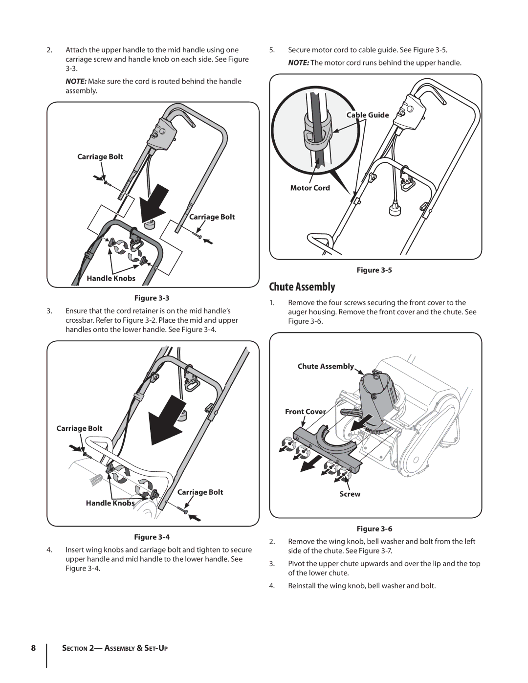
2.Attach the upper handle to the mid handle using one carriage screw and handle knob on each side. See Figure
NOTE: Make sure the cord is routed behind the handle assembly.
Carriage Bolt
![]() Carriage Bolt
Carriage Bolt
Handle Knobs
Figure
3.Ensure that the cord retainer is on the mid handle’s crossbar. Refer to Figure
Carriage Bolt
Carriage Bolt
Handle Knobs
Figure
4.Insert wing knobs and carriage bolt and tighten to secure upper handle and mid handle to the lower handle. See
Figure
5.Secure motor cord to cable guide. See Figure
Cable Guide
Motor Cord
Figure
Chute Assembly
1.Remove the four screws securing the front cover to the auger housing. Remove the front cover and the chute. See
Figure
Chute Assembly
Front Cover
Screw
Figure
2.Remove the wing knob, bell washer and bolt from the left side of the chute. See Figure
3.Pivot the upper chute upwards and over the lip and the top of the lower chute.
4.Reinstall the wing knob, bell washer and bolt.
8
Section 2— Assembly &