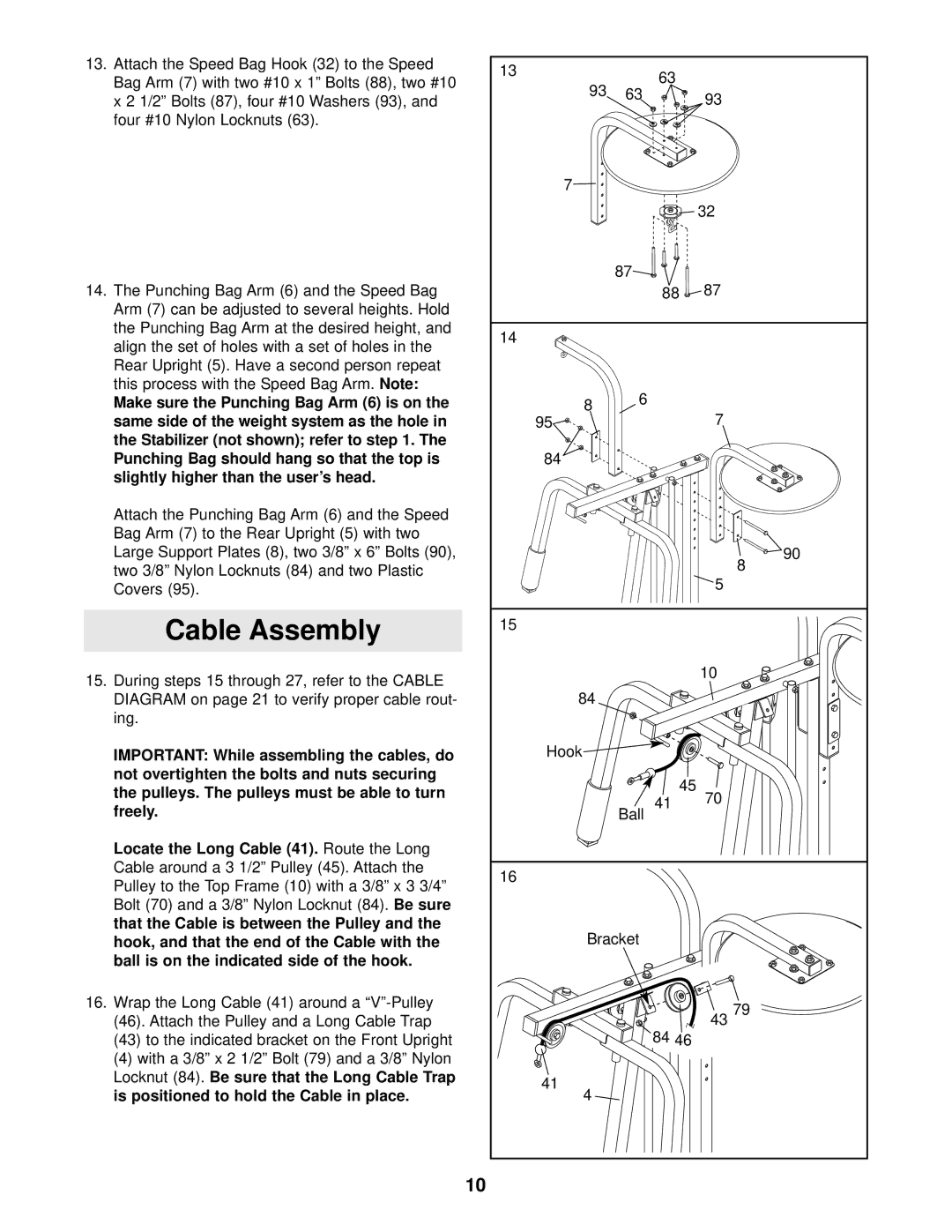
13. Attach the Speed Bag Hook (32) to the Speed | 13 |
| 63 |
|
Bag Arm (7) with two #10 x 1” Bolts (88), two #10 |
|
| ||
93 | 63 |
| ||
| 93 | |||
x 2 1/2” Bolts (87), four #10 Washers (93), and |
| |||
|
|
| ||
four #10 Nylon Locknuts (63). |
|
|
|
|
| 7 |
|
|
|
|
|
|
| 32 |
|
| 87 |
|
|
14. The Punching Bag Arm (6) and the Speed Bag |
|
| 88 | 87 |
Arm (7) can be adjusted to several heights. Hold |
|
|
|
|
the Punching Bag Arm at the desired height, and | 14 |
|
|
|
align the set of holes with a set of holes in the |
|
|
| |
|
|
|
| |
Rear Upright (5). Have a second person repeat |
|
|
|
|
this process with the Speed Bag Arm. Note: |
| 6 |
|
|
Make sure the Punching Bag Arm (6) is on the | 8 |
| 7 | |
same side of the weight system as the hole in | 95 |
|
| |
the Stabilizer (not shown); refer to step 1. The |
|
|
|
|
Punching Bag should hang so that the top is | 84 |
|
|
|
slightly higher than the user’s head. |
|
|
|
|
Attach the Punching Bag Arm (6) and the Speed |
|
|
|
|
Bag Arm (7) to the Rear Upright (5) with two |
|
|
|
|
Large Support Plates (8), two 3/8” x 6” Bolts (90), |
|
|
| 90 |
two 3/8” Nylon Locknuts (84) and two Plastic |
|
|
| 8 |
|
|
| 5 | |
Covers (95). |
|
|
| |
|
|
|
| |
Cable Assembly | 15 |
|
|
|
|
|
|
| |
15. During steps 15 through 27, refer to the CABLE |
|
|
| 10 |
|
|
|
| |
DIAGRAM on page 21 to verify proper cable rout- | 84 |
|
|
|
ing. |
|
|
|
|
IMPORTANT: While assembling the cables, do | Hook |
|
|
|
not overtighten the bolts and nuts securing |
|
| 45 |
|
the pulleys. The pulleys must be able to turn |
|
| 70 | |
|
| 41 | ||
freely. |
| Ball | ||
|
| |||
Locate the Long Cable (41). Route the Long |
|
|
|
|
Cable around a 3 1/2” Pulley (45). Attach the | 16 |
|
|
|
Pulley to the Top Frame (10) with a 3/8” x 3 3/4” |
|
|
| |
|
|
|
| |
Bolt (70) and a 3/8” Nylon Locknut (84). Be sure |
|
|
|
|
that the Cable is between the Pulley and the | Bracket |
|
| |
hook, and that the end of the Cable with the |
|
| ||
ball is on the indicated side of the hook. |
|
|
|
|
16. Wrap the Long Cable (41) around a |
|
|
| 43 79 |
(46). Attach the Pulley and a Long Cable Trap |
|
| 84 46 | |
(43) to the indicated bracket on the Front Upright |
|
|
| |
(4) with a 3/8” x 2 1/2” Bolt (79) and a 3/8” Nylon |
|
|
|
|
Locknut (84). Be sure that the Long Cable Trap | 41 |
|
|
|
is positioned to hold the Cable in place. |
|
|
| |
4 |
|
|
| |
| 10 |
|
|
|
