PRINTED IN USA
IMPORTANTREAD SAFETY RULES AND INSTRUCTIONS CAREFULLY
TROY-BILT LLC, P.O. BOX 361131, CLEVELAND, OH
FORM NO. 770-10598A
FINDING MODEL NUMBER
TABLE OF CONTENTS
Content
ENGINE INFORMATION
Section
1 Safety
Safety Alert Symbol
Training
Antidotes
Section 1 Safety
c. Use slower wheel, tine and engine speeds
Decals
Maintenance and Storage
Operating Symbols
TO AVOID SERIOUS INJURY
Loose Parts List Qty. Description
2 Assembly
Tools/Materials Needed for Assembly
Introduction
Wire
Section 2 Assembly
Adjustment
STEP 4 Connect Forward Interlock Wire Harness
STEP 6 Check Gear Oil Levels
Section 2 Assembly
STEP 7 Add Motor Oil to Engine
STEP 9 Adjust Air Pressure in Tires
STEP 8 Attach Engine Throttle Lever and Cable
Oil Level Hole
STEP 1 Connect the Wire Harness Receptacle
STEP 2 Install the Battery Cables
Battery produces explosive gases
ASSEMBLING THE ELECTRIC START SYSTEM
G F A B E C D
3 Features and Controls
PTO Attachments Feature
Wheels/Tines/PTO Drive Lever
Wheel Speed Lever
Section 3 Features and Controls
Handlebar Height Adjustment Lever
Tines/PTO Clutch Lever
Engine Controls
Section 3 Features and Controls
Keyswitch Starter
Engine Throttle Lever
INTRODUCTION
Pre-Start Checklist
4 Operation
Break-In Operation
Starting the Engine
areas. Temperatures in these areas may exceed 150oF
Section 4 Operation
To help prevent serious personal injury or damage to equipment
Stopping the Engine and Tiller
Cold Weather Operation
Operating the Tiller
Moving the Tiller Forward and Tilling
To Stop the Engine
Moving the Tiller in Reverse
Stopping Reverse Motion
Making Turns
Loading and Unloading the Tiller
Testing the Forward Interlock Safety System
How to Check the Interlock System
Transporting The Tiller Around Your Property
Unloading the Tiller
Changing Speed Belts
Loading the Tiller
Changing Belt From LOW Range to HIGH Range
Section 4 Operation
Choosing Wheel and Tine Speeds
Changing Belt From HIGH Range to LOW Range
TABLE 2-4 WHEEL SPEED AND BELT RANGE SELECTION GUIDE
Use shallow depth regulator settings. Till gradually deeper
Tilling Tips & Techniques
Let the tiller do the work
Suggested tilling patterns
Do not use FAST wheel speed position when on sloped ground
Avoid making footprints
Tilling on slopes
Tilling Tips & Techniques
Clearing the tines
B. Terrace Gardening
Section 4 Operation
Tilling Under Corn
POWER COMPOSTING
Wide-Row Planting
Soil Enrichment Idea
Removing And Replacing The Tine Attachment
PTO POWER UNIT
VERY IMPORTANT
Removing Tine Attachment
Setting Up Stationary Attachments
PTO POWER UNIT OPERATING INSTRUCTIONS
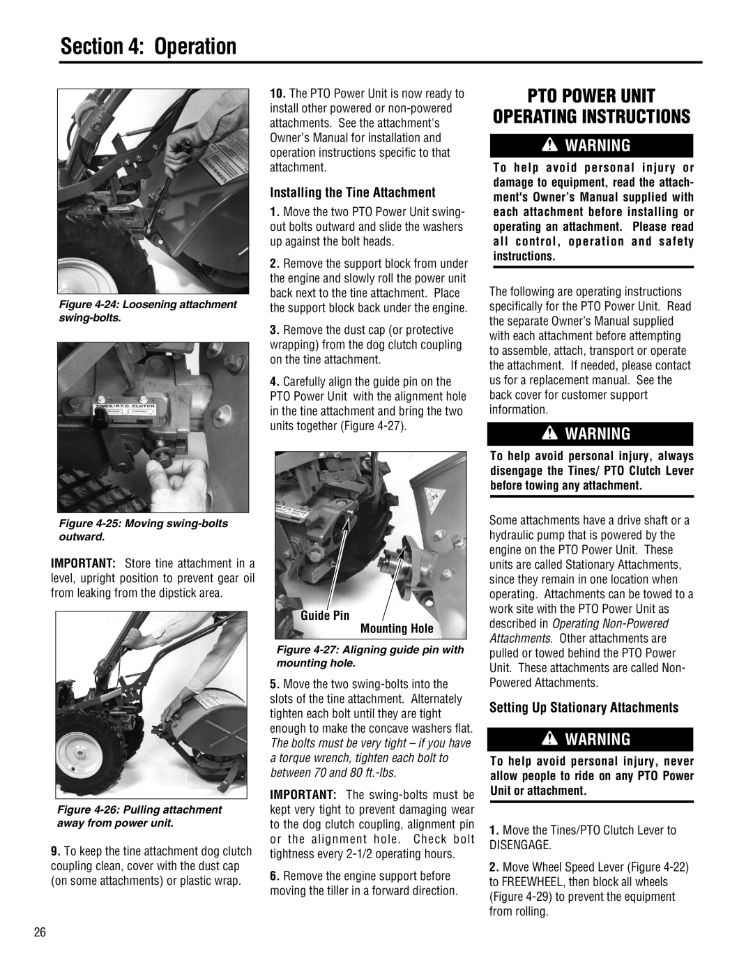
Installing the Tine Attachment
Guide Pin Mounting Hole
Operating Stationary Attachments
Setting Up Non-Powered Attach- ments
Starting The Engine
Stopping the Engine
PROCEDURE
5 Maintenance
REQUIRED MAINTENANCE SCHEDULE
Every
Tiller Lubrication
Section 5 Maintenance
Tighten Bolts and Nuts
Checking for Oil Leaks
Transmission Gear Oil Maintenance
Checking the Power Unit Oil Level
Checking Gear Oil Levels
For Dipsticks With Hot/Cold Markings
Adding or Changing Gear Oil
Checking the Tine Attachment Oil Level
Section 5 Maintenance
Adding Gear Oil to the Tine Attachment Transmission
Adding Gear Oil to the PTO Power Unit Transmission
Draining and Filling the PTO Power Unit Transmission
Draining and Filling the Tine Attachment Transmission
How to Measure Belt Tension
Drive Belt Maintenance
Measuring and Adjusting Drive Belt Tension
5/16 1/4 Belt Adjustment Tool
Replacing the Drive Belt
Replacing the Drive Belt
Removing the Belt
Section 5 Maintenance
Section 5 Maintenance
Reverse Drive System Maintenance
Reverse Disc Inspection
Checking and Adjusting Reverse Disc
Checking and Adjusting Reverse the Drive System
Installing a New Reverse Disc
Replacing the Reverse Disc
Adjustment Bolt Jam Nut
Bolo Tine Maintenance
Adjusting Reverse Drive
Checking Tines for Wear
Removing Tine Holder Assembly
Single Tine Replacement
Removing and Replacing A Tine Holder Assembly
Replacing Tines Holder Assembly
Air Cleaner Maintenance
Tine Shaft Maintenance
Tire and Wheel Maintenance
Spark Plug Maintenance
Storing Your Tiller
Inspecting Forward Interlock Wiring System
Testing the Forward Interlock Wiring System
Section 5 Maintenance
PROBLEM
Appendix A Troubleshooting
Troubleshooting Procedures
CHECK OR TEST
5 Tines Turn, But Wheels Won’t
Appendix A Troubleshooting
See Troubleshooting the Forward Interlock Safety System in Section
Troy-Bilt PTO Log Splitter
Appendix B Attachments & Accessories
Wheel Weights
Dozer/Snow Blade Attachment
PART
6 Parts List
WHEELS/TINES/PTO DRIVE LEVER & YOKE ASSEMBLY
DESCRIPTION
DESCRIPTION
Parts List
FORWARD INTERLOCK SYSTEM
DESCRIPTION
PART
HANDLEBAR ASSEMBLY
Parts List
DESCRIPTION
PART
DEPTH REGULATOR & TINE HOOD ASSEMBLIES
Parts List
DESCRIPTION
See Page See Page
WHEEL SPEED LEVER, BELT DRIVE SYSTEM, ENGINES, WHEELS
Parts List
ENGINES AND ENGINE MOUNT
WHEEL SPEED LEVER
BELT DRIVE SYSTEM
WHEEL & TIRE ASSEMBLIES
See Page
POWER UNIT TRANSMISSION ASSEMBLIES
Parts List
BRACKET ASSEMBLIES
DRIVE SHAFT ASSEMBLY
PINION SHAFT ASSEMBLY
continued on page
MODELS 682J & E682L
POWER UNIT TRANSMISSION ASSEMBLIES Continued from page
Parts List
See Page
MISCELLANEOUS PARTS
TRANSMISSION HOUSING
TRANSMISSION ASSEMBLY
Parts List
THAT CAN NOT BE REUSED WITHOUT RISKING THE
TILLER ATTACHMENT TRANSMISSION ASSEMBLIES
NOTE 1 THESE SCREWS HAVE A SPECIAL SEALING DESIGN
LOSS OF TRANSMISSION OIL. IF THESE SCREWS
Parts List
TILLER DRIVE SHAFT ASSEMBLY
TRANSMISSION HOUSING AND DIPSTICK
TRANSMISSION ASSEMBLY
BOLO TINE ASSEMBLIES
Parts List
DESCRIPTION
CUSTOM TILLING TINES
Parts List
DESCRIPTION
MODEL E682L
ELECTRIC START SYSTEM
Parts List
DESCRIPTION
Parts List
PART
PART
DESCRIPTION
BUMPER ATTACHMENT
Parts List
PART
Page
Page
Page
TROY-BILT TILLER LIFETIME LIMITED WARRANTY
TROY-BILT LLC, P.O. Box 361131, Cleveland, Ohio 44136-0019