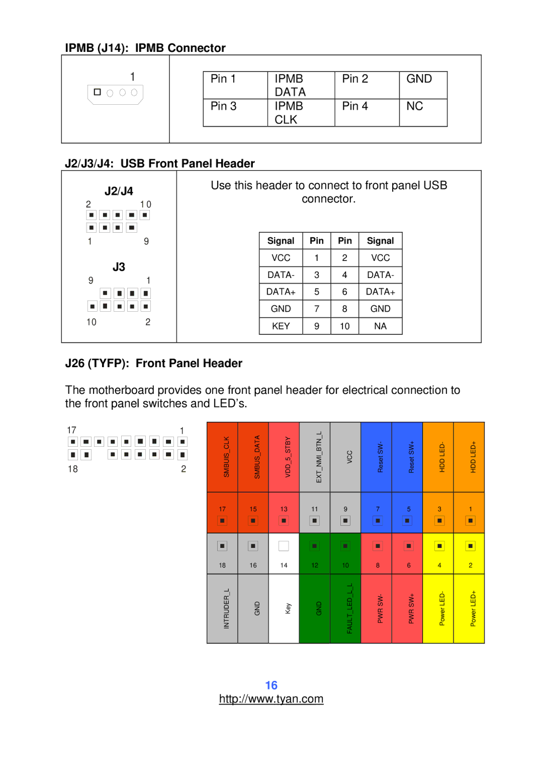
IPMB (J14): IPMB Connector
1
Pin 1 | IPMB | Pin 2 | GND |
| DATA |
|
|
Pin 3 | IPMB | Pin 4 | NC |
| CLK |
|
|
J2/J3/J4: USB Front Panel Header
J2/J4
210
1 9
J3
91
10 2
Use this header to connect to front panel USB
connector.
Signal | Pin | Pin | Signal |
|
|
|
|
VCC | 1 | 2 | VCC |
|
|
|
|
DATA- | 3 | 4 | DATA- |
|
|
|
|
DATA+ | 5 | 6 | DATA+ |
|
|
|
|
GND | 7 | 8 | GND |
|
|
|
|
KEY | 9 | 10 | NA |
|
|
|
|
J26 (TYFP): Front Panel Header
The motherboard provides one front panel header for electrical connection to the front panel switches and LED’s.
171
182
| SMBUIS CLK |
| SMBUS DATA |
| VDD 5 STBY |
| EXT NMI BTN L |
| VCC |
| Reset SW- |
| Reset SW+ |
| HDD LED- |
| HDD LED+ | |||||||||
|
|
|
|
|
|
|
|
|
|
|
|
|
|
|
|
|
|
|
|
|
|
|
|
|
|
|
17 |
| 15 |
| 13 |
| 11 |
| 9 |
| 7 |
| 5 |
| 3 |
| 1 |
| |||||||||
|
|
|
|
|
|
|
|
|
|
|
|
|
|
|
|
|
|
|
|
|
|
|
|
|
|
|
|
|
|
|
|
|
|
|
|
|
|
|
|
|
|
|
|
|
|
|
|
|
|
|
|
|
|
|
|
|
|
|
|
|
|
|
|
|
|
|
|
|
|
|
|
| ||||||||
|
|
|
|
|
|
|
|
|
|
|
|
|
|
|
|
|
|
|
|
|
|
|
|
|
|
|
| 18 |
|
| 16 |
|
| 14 |
|
| 12 |
|
| 10 |
|
| 8 |
|
| 6 |
|
| 4 |
|
| 2 |
|
|
|
|
|
|
|
|
|
|
|
|
|
|
|
|
|
|
|
|
|
|
|
|
|
|
|
|
| INTRUDER L |
| GND |
| Key |
| GND |
| FAULT LED L L |
| PWR SW- |
|
| PWR SW+ |
|
| Power LED- |
|
| Power LED+ |
| |||||
|
|
|
|
|
|
|
|
|
|
|
|
|
|
|
|
|
|
|
|
|
|
|
|
|
|
|
16
http://www.tyan.com