1 GAS-FIRED WATER BOILER SERIES 2 — Boiler Manual

Prepare boiler location (continued)

Prevent combustion air contamination

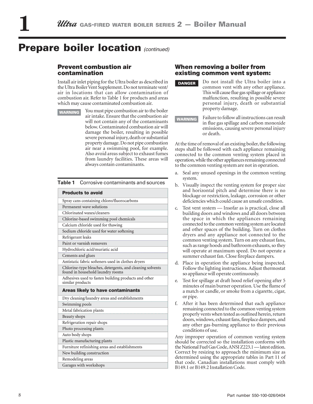
Install air inlet piping for the Ultra boiler as described in the Ultra Boiler Vent Supplement. Do not terminate vent/ air in locations that can allow contamination of combustion air. Refer to Table 1 for products and areas which may cause contaminated combustion air.

You must pipe combustion air to the boiler air intake. Ensure that the combustion air will not contain any of the contaminants below. Contaminated combustion air will damage the boiler, resulting in possible severe personal injury, death or substantial property damage. Do not pipe combustion air near a swimming pool, for example. Also avoid areas subject to exhaust fumes from laundry facilities. These areas will always contain contaminants.

Table 1 Corrosive contaminants and sources

When removing a boiler from existing common vent system:

Do not install the Ultra boiler into a common vent with any other appliance. This will cause flue gas spillage or appliance malfunction, resulting in possible severe personal injury, death or substantial property damage.

Failure to follow all instructions can result in flue gas spillage and carbon monoxide emissions, causing severe personal injury or death.

At the time of removal of an existing boiler, the following steps shall be followed with each appliance remaining connected to the common venting system placed in operation, while the other appliances remaining connected to the common venting system are not in operation.

a.Seal any unused openings in the common venting system.

b.Visually inspect the venting system for proper size and horizontal pitch and determine there is no blockage or restriction, leakage, corrosion or other deficiencies which could cause an unsafe condition.

c.Test vent system — Insofar as is practical, close all building doors and windows and all doors between the space in which the appliances remaining connected to the common venting system are located and other spaces of the building. Turn on clothes dryers and any appliance not connected to the common venting system. Turn on any exhaust fans, such as range hoods and bathroom exhausts, so they will operate at maximum speed. Do not operate a summer exhaust fan. Close fireplace dampers.

d.Place in operation the appliance being inspected. Follow the lighting instructions. Adjust thermostat so appliance will operate continuously.

e.Test for spillage at draft hood relief opening after 5 minutes of main burner operation. Use the flame of a match or candle, or smoke from a cigarette, cigar, or pipe.

f.After it has been determined that each appliance remaining connected to the common venting system properly vents when tested as outlined herein, return doors, windows, exhaust fans, fireplace dampers, and any other gas-burning appliance to their previous conditions of use.

Any improper operation of common venting system should be corrected so the installation conforms with the National Fuel Gas Code, ANSI Z223.1 — latest edition. Correct by resizing to approach the minimum size as determined using the appropriate tables in Part 11 of that code. Canadian installations must comply with B149.1 or B149.2 Installation Code.

8

Part number 550-100-026/0404

Page 8
Image 8
Ultra electronic 105, 80, 155 Prevent combustion air contamination, When removing a boiler from existing common vent system

230 & -310, 105, 155, 80 specifications

Ultra Electronics, a recognized leader in advanced electronic systems, has developed various innovative products catering to different fields, particularly defense, aerospace, and security. Among its notable offerings are the Ultra 230 and demographic models such as the -310, -105, -155, and -80, each designed to meet specific operational requirements and challenges.

The Ultra 230 is renowned for its superior processing capabilities, which leverage high-performance computing to manage complex tasks efficiently. This platform integrates multifaceted technologies like electronic warfare, communications, and sensor data fusion, ensuring that users have real-time information for informed decision-making. The design emphasizes modularity, allowing end-users to customize the system according to their mission profiles.

The Ultra 310 variant extends the functionalities of the 230, providing enhanced connectivity options. Its robust communication interfaces facilitate seamless integration with various networks, ensuring effective data exchange across multiple platforms. This model is particularly effective in joint operations where interoperability is critical among allied forces.

Ultra's -105 model is designed specifically for ground vehicles, offering ruggedness and resilience under harsh conditions. It features advanced environmental protection, allowing it to withstand dust, moisture, and vibration. This makes the -105 ideal for tactical military applications where reliability in diverse terrains is crucial.

The -155 model emphasizes versatility and adaptability, boasting a wide range of components and configurations. This allows for easy upgrades and maintenance, enabling military and defense organizations to stay current with technological advancements without significant investments in new equipment.

Lastly, the Ultra 80 is aimed at the aviation sector, focusing on lightweight design without compromising on power or functionality. It employs cutting-edge materials that enhance performance while reducing overall weight, making it ideal for aerial applications.

In summary, Ultra Electronics' products - the 230, -310, -105, -155, and -80 - showcase a commitment to innovation and operational excellence. Each model brings forth unique features and technologies, ensuring they meet the diverse needs of their users across various industries. From advanced processing capabilities to rugged designs suitable for any environment, Ultra Electronics continues to push the boundaries of technological advancement, maintaining its position as a frontrunner in the electronic systems market.