Getting Started
| DC 13.8V |
| Auxillary | Antenna | Telescoping | |
| Jack |
| Jack |
| Jack | Antenna |
| AC Adapter/ |
|
|
|
|
|
| Charger |
|
|
|
|
|
| (AC580U) |
|
|
|
|
|
|
|
| OFF ON |
|
|
|
Standard | DC13.8V | AUX | ENTER LOCK |
|
| ANT |
120V |
|
|
|
|
| |
|
|
|
|
|
| |
AC Wall Outlet |
|
|
|
|
|
|
|
| Plug |
| |||
|
|
|
|
| ||
|
|
|
| Switch |
|
|
Base Installation
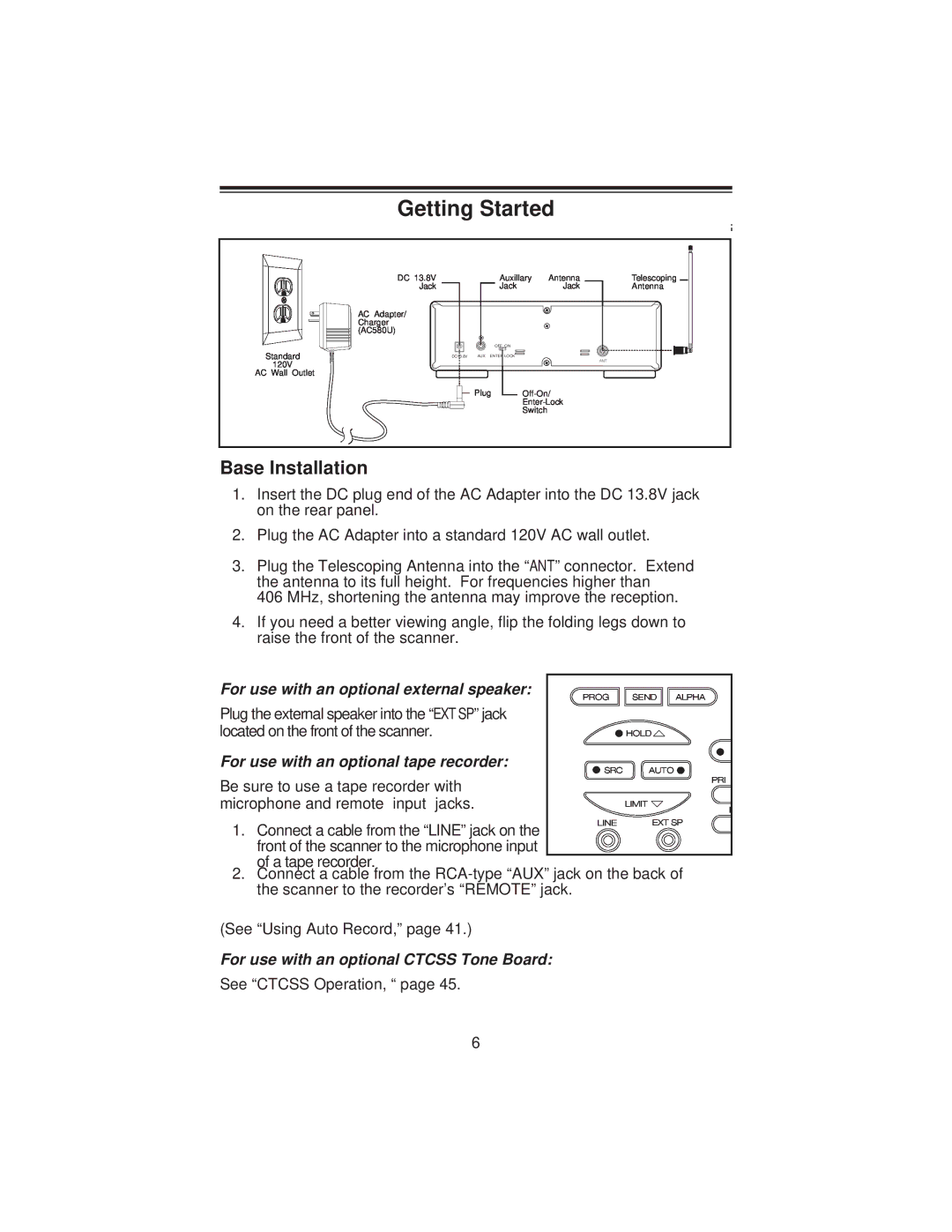
1.Insert the DC plug end of the AC Adapter into the DC 13.8V jack on the rear panel.
2.Plug the AC Adapter into a standard 120V AC wall outlet.
3.Plug the Telescoping Antenna into the “ANT” connector. Extend the antenna to its full height. For frequencies higher than
406 MHz, shortening the antenna may improve the reception.
4.If you need a better viewing angle, flip the folding legs down to raise the front of the scanner.
For use with an optional external speaker: | PROG | SEND ALPHA |
Plug the external speaker into the “EXT SP” jack |
|
|
located on the front of the scanner. |
| HOLD |
For use with an optional tape recorder: | SRC | AUTO |
| ||
Be sure to use a tape recorder with |
| PRI |
|
| |
microphone and remote input jacks. |
| LIMIT |
| L |
1. Connect a cable from the “LINE” jack on the front of the scanner to the microphone input of a tape recorder.
LINE
2. Connect a cable from the
(See “Using Auto Record,” page 41.)
For use with an optional CTCSS Tone Board:
See “CTCSS Operation, “ page 45.
6
