Connecting the radio
To operate correctly, your radio requires two electrical connections:
xx | providing it with power from the boat’s electrical system | |
xx | connecting a | |
|
| |
Power Supply Requirements | VHF Antenna Requirements | |
Nominal 13.8 VDC power supply with a | Male | |
negative ground (9.5 VDC to 15.8 VDC). | 50 Ω impedance | |
Power leads should be kept as short as | Minimum 4 foot, 3 dB rated antenna for | |
possible. A direct connection to the power | sailboats or 8 foot, 6dB rated antenna for | |
supply is ideal. | powerboats | |
Minimum of #14 AWG copper wire for | Minimum | |
extensions up to 20 feet, 12 AWG wire for | leads up to 20 feet, | |
extensions from 20 to 35 feet, or 10 AWG | leads from 20 to 35 feet, or | |
wire for extensions from 35 to 60 feet. | antenna leads from 35 to 60 feet. | |
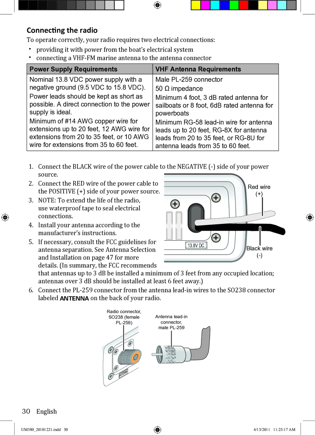
1.Connect the BLACK wire of the power cable to the NEGATIVE
2. Connect the RED wire of the power cable to the POSITIVE (+) side of your power source.
3. NOTE: To extend the life of the radio, use waterproof tape to seal electrical connections.
4. Install your antenna according to the manufacturer’s instructions.
5. If necessary, consult the FCC guidelines for |
|
| |
13.8V DC | Black wire | ||
antenna separation. See Antenna Selection | |||
| |||
and Installation on page 47 for more |
| ||
|
|
details. (In summary, the FCC recommends
that antennas up to 3 dB be installed a minimum of 3 feet from any occupied location; antennas over 3 dB should be installed at least 6 feet away.)
6.Connect the
Radio connector, | Antenna | ||
SO238 (female | |||
connector, | |||
|
| male | |
|
|
|
|
|
|
|
|
|
|
|
|
30English
UM380_20101221.indd 30
4/13/2011 11:25:17 AM
