Product Information Announcement
Page
Hardware Configuration Guide
Page
Unisys
Page
Hardware Configuration
Guide
Page
Contents
Configuring System Options
Contents
Configuring I/O Cabinets and Channel Racks
Contents Configuring the Input/Output Module
Configuring the Servers
Configuring the Private Maintenance Hub and Public
Connecting Other Host Systems
Configuring Optional and Recommended UPS
Figures
Figures
Tables
Tables
Purpose
Scope
Audience
Prerequisites
Organization
How to Use This Guide
About This Guide
Configuring the Input/Output Module
Related Product Information
Industry Publications
Introduction
Features
What Product Models Are Covered
System Architecture
Technology Enhancements
Single Domain
System Partitioning
Dual Domain
Hardware Overview
Type of Computing System
System Cabinet
Hardware Overview
I/O Subsystem
Hardware Overview Expansion Sections
Svga Monitor and Keyboard with Mouse
Rack-Mounted Devices
System Cabinet Organization
Supported Peripherals
System Components
System Cabinet Organization Other I/O Devices
Acronyms for System Components
System Components
Acronym Component Name
WindowsServer CNT
Front View
System Cabinet PCA Locations for NX5820 K
NT a
SCP B
How This Section Is Organized
NX5820 Products
Single-Domain, Single-Processor Sdsp NX5821 Models 31 to
Dual-Domain, Multiple-Processor Ddmp NX5822 Models 32 to
NX5820 Products
ClearPath Enterprise Server NX5820 Product Models
NX5820 Product Configurations
NX5820 Product Configurations
Component Description NX5821 Models Style
Common Components
Msua BD, 1 CHIPSET, 4 REQUESTER, 192 MB
Central Equipment Section
Server Expansion Section
Component Description NX5822 Models Style
Functional S/W, IP Emulation NX5822-32
Functional S/W, IP Emulation NX5822-73
Functional S/W, IP Emulation NX5822-78
CEC SCP
NX5820 Companion Styles
NX5820 Companion Package Style
Component Description Package Styles NX5821-1X NX5822-2X
NX5820 K Products
Single-Domain, Single-Processor Sdsp NX5821 BAS Models
Dual-Domain, Dual Processor Dddp NX5822 BAS Models
NX5820 K Products
Dual-Domain, Multiple-Processor Ddmp NX5822 BAS Models
Three to ten processor modules PM depending on model
ClearPath Enterprise Server NX5820 K Product Models
NX5820 K Single-Domain, Single-Processor Sdsp Models
NX5820 K Product Configurations
NX5820 K Product Configurations
Package Style NX5821-BAS Component Style Description Qty
PCK104-SKB Keyboard PCK1-EXT CABLE, M to F PS2
Central Equipment Section
Lists component styles for these models
Processors
DOM1 Card COMPL, CIOM1 CIOM, 1 Kiub
Server Expansion Section
NX5820 K Processor Package Style
NX5820 K Processor Package Styles
Dual-Domain, Multi-Processor Configurations
Power Supply 3U, 360 VDC to
Power Layout and Requirements
Redundant Power/Cooling
Cables
Cables
NX5820 System Upgrades
NX5820 System Upgrades
10. NX5820 System Upgrade Options Summary
Upgrade Type Converts See From
10. NX5820 Upgrade Diagram
Package Converts Component Style
Style Style Description
Package Converts Component Style From Style Description
Components required for all above package styles
NX5820 K System Upgrades
NX5820 K System Upgrades
11. NX5820 K Upgrade Diagram
Upgrade Type Converts Package Style From
14. NX5820 K Upgrade Options Summary
Package Component Qty Style
Component Style Description Qty Package Style NXD58211-2D2
Components required for above package style
MSK208-MEM
Component Style Description Qty Package Style NXU58223-2D4
Package Style NXU58224-2D5
Package Style NXU58225-2D61
Package Style NXU58226-2D72,3
Configuring System Options
NX5820 and NX5820 K Memory
Basic Memory Board Configuration By System Style
NX5820 and NX5820 K Memory Styles and Upgrade Components
NX5820 and NX5820 K Memory
System Style Memory Style Basic Quantity Maximum Quantity
Style Description MSK208 Style Memory
MSK412 Style Memory
MSA104 Style Memory
MSA104 Style Memory
MSK208 Style Memory
MSK208 Style Memory
MSK208 Board Layout
MSK412 Style Memory
MSK412 Style Memory
MSK412 Board Layout
Memory Slot Locations
Memory Slot Locations
Memory Card Slot Locations
Configuring Redundant SCP for the NX5820 and NX5820 K
IOM Channel Expansion
IOM Channel Expansion
Redundant System Console Package Styles
Configuring Additional Displays
Configuring Redundant Switching Hubs
Configuring Redundant Switching Hubs
Configuration Guidelines for SCP Monitors and ODW Displays
Configuring Operator Display Workstations
Configuring Additional Displays
Guidelines for Configuring SCP Monitors and ODW Displays
Configuration Guideline
Redundant Power for the NX5820 and NX5820 K
Configuring Additional OSS7000 Devices
Work Space
Converting From NX5820 to NX5820 K Systems
Converting From NX5820 to NX5820 K Systems
Conversion Package Styles for NX5820 to NX5820 K Systems
NXM582272-72K NX5822-72 NX5822-2D2/PL7 Migration
How to Use This Section
Configuring I/O Cabinets
Configuring I/O Cabinets
Configuration Guidelines for I/O Cabinets
Cabinet Styles
Status Style Description
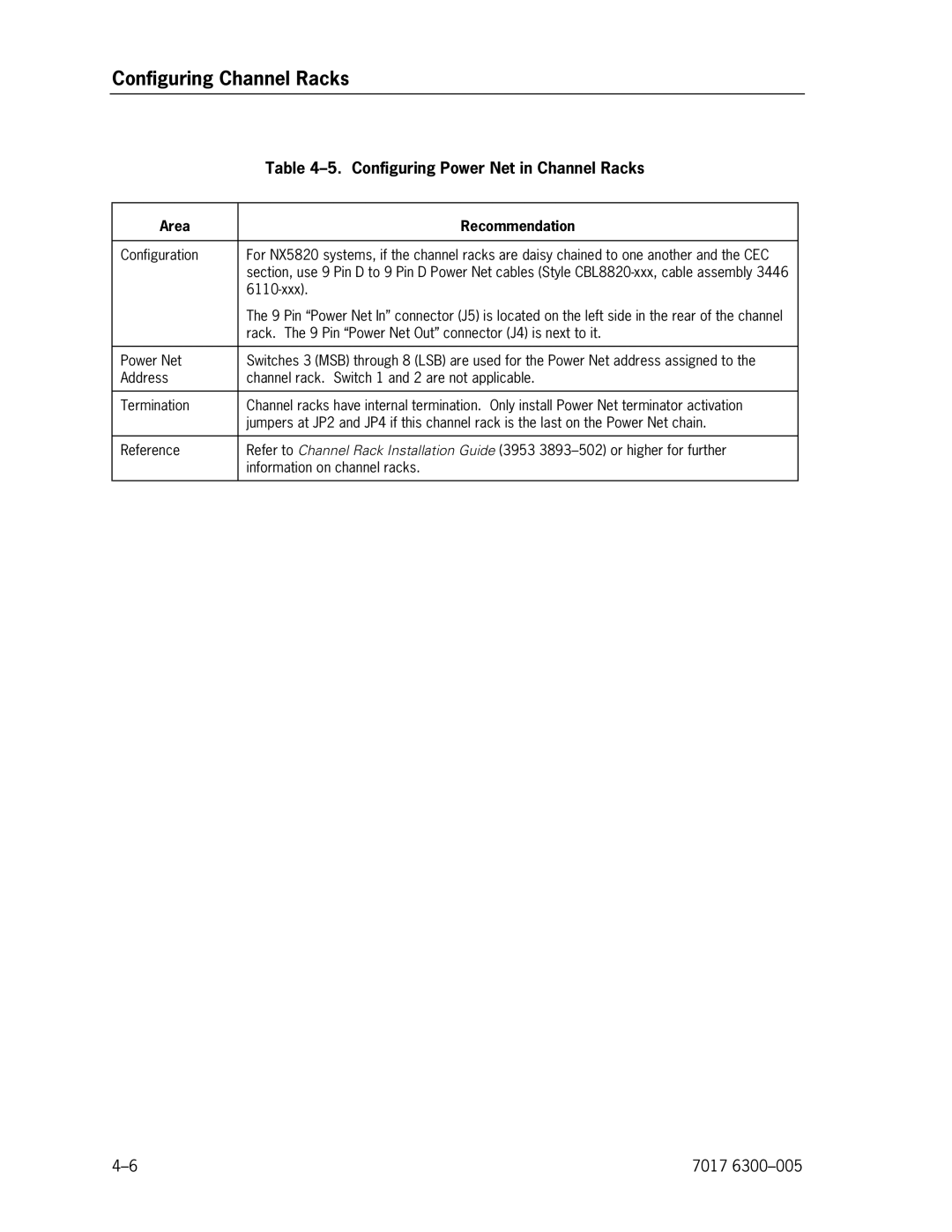
Configuring Channel Racks
Configuring Channel Racks
Channel Rack Components
RM5-CA5
Guidelines for Configuring Channel Racks
Area Rule/Recommendation
Configuring Power Net in Channel Racks
Area Recommendation
Configuring the Input/Output Module
Introduction
IOM Logical Organization
How the IOM Is Organized
How the IOM Is Organized
IOM Physical Organization
NX5820 K IOM Organization
Card Module Assembly for NX5820
First Ciom Per Domain
IOM Options
CMF External Connectivity
Name
Ciom Upgrade
Name
Configuring Channels
Configuring Channels
Styles Offered
Supported Channel Adapter Types
Assigning Channel Loads
Ciom CS-Bus Channel Loading
Bus Demand Factor Channel Type
Maximum Connectivity
Configuration Guidelines
CIOM/CMF/CS-BUS and Channel Diagram
Guidelines for Configuring Channels
20 CS buses per domain for NX5820 K
Total Channels for NX5820 K System
Total Channels for NX5820 System
Reserved channels per domain
NX5820 Channel Assignments and Configurations
Configuration Diagrams
Name/Use Description
For NX5820 K, use for Multi-IOU functionality only
For NX5820, IOU functionality only
Pcithru Feature Card
Pcithru Feature Card
Pcithru Slot Versus PCI Bridge Jumper Positions
Pcithru Channel Slot No PCI Bridge Jumper Position
Configuring QIC Tape and CD-ROM
Configuring QIC Tape and CD-ROM
7017
Configuring the Servers
VX1305 Servers
VX1305 Basic Features
VX1305 Servers
Basic Features, VX1305 Servers
Min Max Std
Road Map for Ordering VX1305 Servers
Server Components
Basic Server Components
Add-On Processor Board
VX1305-BSE/-BSU Basic Components
Add-On Processor Board, VX1305 Servers
Component Description Qty Style Name
Additional Memory Packages
Connection Packages and Optional PCI Thru Card
Memory Packages, VX1305 Servers
Connection Package Components, VX1305 Servers
Optional User Access Components
Single-Server to Multi-Server Upgrades
VX4000-CP3 Optional User Access Components
Style Number Qty Description
Configuration Guidelines, VX1305 Servers
VX1305 Server CS Bus Cable Connection
VX1505 Servers
VX1505 Basic Features
VX1505 Servers
Basic Features, VX1505 Servers
VX1505-BSE Processor Requirements
No. of Installed
Required
Road Map for Ordering VX1505 Servers
10. VX1505-BSE/-BSU Basic Components
Basic Server Components and Optional Redundant Power Supply
Component Style Description Qty Name
Processors
Memory Packages
11. Processors, VX1505 Servers
12. Memory Packages, VX1505 Servers
13. Connection Package Components, VX1505 Servers
NX5820-1NT NXU5810-NT
Optional User Access Components
15. Configuration Guidelines, VX1505 Servers
VX1505 Server CS Bus Cable Connection
ES5085R Servers
Basic Features
ES5085R Servers
16. Basic Features, ES5085R Servers
US/Canada contains NTE4008-L
Server Components
Road Map for Ordering ES5085R Servers
17. Processors, ES5085R Servers
18. Memory Packages, ES5085R Servers
Component Description Qty Style Number Processors
Style Number Qty Description Memory
19. Connection Package Components, ES5085R Servers
Connection Packages and Optional PCI
NX508151-1NT NXU508151-NT
Configuration Guidelines ES5085R
VX4000-CP3 Optional User Access Components, ES5085R
ES2024R Servers
ES2024R Servers
21. Basic Features, ES2024R Servers
NXS840-EJX
Server Components
Road Map for Ordering ES2024R Servers
23. Memory Packages, ES2024R Servers
22. Processors, ES2024R Servers
Component Style Description Qty Number Processors1
24. Connection Package Components, ES2024R Servers
NX502141-1NT NXU502141-NT
Configuration Guidelines ES2024R
VX4000-CP3 Optional User Access Components, ES2024R
ES5044R Servers
ES5044R Servers
26. Basic Features, ES5044R Servers
Server Components
Road Map for Ordering ES5044R Servers
28. Memory Packages, ES5044R Servers
27. Processors, ES5044R Servers
Component Style Description Qty Number Processors 1,2
29. Connection Package Components, ES5044R Servers
NX504141-1NT NXU504141-NT
Configuration Guidelines ES5044R
VX4000-CP3 Optional User Access Components, ES5044R
Using Public Switching LAN a Bay Network 350 T
Port Destination Comments
To customer’s public LAN
Using Public Switching LAN B Bay Network 350 T
Using Public Switching LAN B Cisco 2924 XL
Using Public Switching LAN a Cisco 2924 XL
Destination Comments
7017
7017
To customer’s public LAN Optional
NT Server a NT Server C Optional NT Server E NT Server G
Using Public Switch LAN a Cisco 2924 XL
Domain 0 LAN Domain 1 LAN
Configuring Optional and Recommended UPS
Configuring Optional and Recommended UPS
35. UPS Options
Expansion Box Options
VX1305-BSE/BSU Servers
36. Status Selection Between SCP’s and Servers
VX1505-BSE/BSU Servers
SCP
SER
13. SCP to UPS Status Cable
Configuring Optional and Recommended UPS
Connecting Other Host Systems
Guidelines for Connecting Other Host Systems
Connecting Other Host Systems
Glossary
Glossary
Dimm
LAN
Msua
UPS
Glossary-6 7017
Index
Index
Components
Index-3
Index-4 7017
Page
70176300-005