2.4 Triggering the Scanner Module
The PT-500 can be used with a built-in integrated laser or CCD scanner module. To use the scanner, just point the scanner window at a barcode and press the trigger that activates the scanner. A short beep from the buzzer and flashing red LED indicator on top of the LCD display indicates when the scanning is successful.
2.5 Interface Port
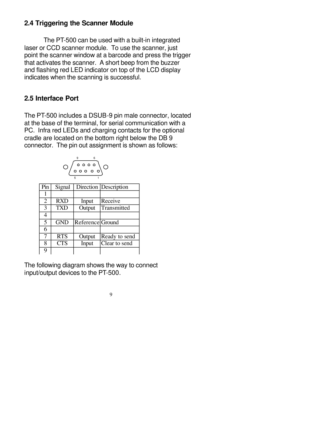
The PT-500 includes a DSUB-9 pin male connector, located at the base of the terminal, for serial communication with a PC. Infra red LEDs and charging contacts for the optional cradle are located on the bottom right below the DB 9 connector. The pin out assignment is shown as follows:
| | 9 | 6 | |
| | 5 | 1 | |
Pin | Signal | Direction | Description |
1 | | | | |
2 | RXD | | Input | Receive |
3 | TXD | | Output | Transmitted |
4 | | | | |
5 | GND | Reference Ground |
6 | | | | |
7 | RTS | | Output | Ready to send |
8 | CTS | | Input | Clear to send |
9 | | | | |
The following diagram shows the way to connect input/output devices to the PT-500.
9